
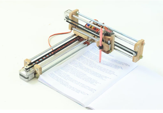
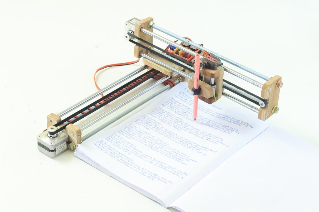
A CNC writing machine is an innovative automated device designed to write text or draw intricate designs on paper. This sophisticated machine functions by utilizing two main axes: the x-axis and the y-axis. These axes work in tandem to move the writing instrument precisely across the surface of the paper, allowing it to create detailed and accurate 2D images.
The x-axis controls the horizontal movement, guiding the pen or marker from left to right and back, while the y-axis manages the vertical movement, directing the pen up and down the page. Together, these coordinated movements enable the CNC writing machine to reproduce any text or design with precision and consistency.
By following programmed instructions, the CNC writing machine can replicate complex patterns, write custom messages, or even recreate detailed drawings. This makes it an invaluable tool for various applications, from artistic endeavors to practical tasks such as labeling or creating custom stationery.
The beauty of a CNC writing machine lies in its ability to transform digital designs into physical creations, bridging the gap between technology and traditional writing or drawing. Whether for personal use, educational purposes, or professional projects, this device offers a seamless way to bring digital concepts to life on paper.
Supplies


We need following materials to make writing machine.
Mechanical Parts :
- Wood
- 8 mm Threaded Rod 31 cm long (2 pcs)
- 8 mm Threaded Rod 38 cm long (2 pcs)
- 8 mm Plain Steel Rod 30 cm long (4 pcs)
- 8 mm Plain Steel Rod 6 cm long (2 pcs)
- LM8UU Slider bearing (6 pcs)
- F623ZZ 10x4x3 mm bearing (4 pcs)
- Stepper motor Pulley GT2 (2 pcs)
- GT2 6mm Belt 1.5 meter
- 8 mm Nut (16 pcs)
- 3mm screw
Electrical Parts :
- Arduino Uno (1 pc)
- CNC Shield V3 Expansion board (1 pc)
- A4988 Stepper Motor Driver (2 pcs)
- Nema 17 Stepper Motor ( 2 pcs)
- SG90 Servo Motor (1 pc )
- 12 Volt 1 A Adapter
- 2 pin Short Jumper ( 6 pcs )
- Stepper Motor Wire ( 2 pcs)
- Mg90 servo motor extension wire (1 pc)
- Type B Arduino Cable
Tools :
- Drill Machine
- Computer
- Scale and Pen
- Saw
- Screwdriver
Step 1: Cutting Wood


As seen in the picture, take a long wood strip that is 45 mm broad and cut it into 75 mm.
Mark a 75 mm line with a pen first, then cut it with a saw. Make four identical cuts, then verify that they are precisely 45 mm broad and 75 mm long.
Step 2: Make Holes


At this point, mark four locations to drill 8 mm holes for steel rods. Mark four points ten millimeters from the corner and use an 8 mm drill bit in your drill machine. As seen in the photos, carefully drill each of the four holes.
Next, create a single, rectangular cutout at the top, as seen in the picture, and round the corner using sand paper.
Step 3: Make X and Y Axis Slider


Take out two 31-cm threaded rods, two 38-cm threaded rods, and four 30 cm steel rods. Now, feed an 8 mm nut through the 31 cm threaded rods and insert in to bottom wooden holes. Take another nut now, and slowly tighten both of them. Next, arrange the other end in this manner.
Create a framework similar to this for the other two threaded rods.
Step 4: Make Sliding Mechanism


Now, pass LM8UU bearings through all of the 30 cm long, 8mm steel rods. After that, feed the rods into the wooden components’ top holes as indicated by the drawings.
Two axes are now created. Y is the long axis while x is the short axis.
Step 5: Make Pen Holder Slider


Now, cut three 20 mm long and one 45 mm long wooden strips. Create two holes in a wooden block measuring 45 mm by 20 mm. Next, drill the same holes in a second wooden block.
Right now Using 65 mm steel rods, insert the LM8UU bearing through the rods and into the holes as shown in the pictures.
Attach this structure to a wooden block of 45 mm by 65 mm.
Step 6: Pen Holder


Drill a 3 mm hole in the pen holder slider’s center, as shown in the picture. Take a 45 x 20 mm block now, and attach one thread as seen in the photo. After that, insert the thread into the 3 mm hole and stick the block to the LM8UU Bearings.
Step 7: Complete X and Y Axis


Now, place a wooden block on the Y axis of the LM8UU bearings and the pen holder on the X axis of the LM8UU bearings.
Check that the X and Y axis sliders are operating correctly now.
Step 8: Attach Stepper Motor


Now grab two GT2 stepper motor pulleys and two Nema 17 stepper motors. Attach the stepper motor to the wooden side of the X axis by applying glue to one side, as shown in the photo. Place the second stepper motor on the wooden side of the Y axis.
Using a key, insert the GT2 pulleys into the stepper motor shaft.
Step 9: F623ZZ Bearings


Create a 3 mm hole in the center of the wooden block on the right side, then insert two F623ZZ bearings using a 3 mm bolt. Fit in this manner along the X and Y axes.
Step 10: GT2 Belt Placement


Place tiny wooden pieces on the slider’s rear as shown in the picture. Next, take a 70 cm long GT2 6mm belt and attach it according to the Slider X and Y photos.
Step 11: Stepper Motor Wire


To get the belt tight, now tighten the nuts on the threaded rods. Next, use the stepper motor wire to move spirally on the Y axis threaded rod as shown in the picture.
Step 12: Controller


To build the controller, you’ll need an Arduino Uno, a CNC Shield V3 Expansion board, two A4988 Stepper Motor Drivers, and six short jumpers.
As shown in the picture, install the CNC Shield V3 Expansion board to the Arduino Uno. Next, attach a short jumper to the CNC shield as indicated by the diagram. As seen, insert the last two A4988 drivers into the CNC shield.
Step 13: Placement of Controller


Now, using a glue gun, apply some glue to the Y-axis wooden block. Position the controller on top of it and let it cool.
Step 14:


Now, use glue to attach the X and Y axes. Put the MG90 Servo motor on the pen holder as shown in the illustration. Next, insert the thread into the shaft coupling and secure the servo motor. Trim extra thread, then fasten rubber band as shown in the image.
Step 15: Pen Mount


Now take a geometry rounder and use a cutter to cut the pen mount.Using adhesive, attach this pen mount straight on the pen holder.
Step 16: Wiring


Refer to the wiring using pictures now, and connect the stepper motor wire to the CNC shield. Next, using the pictures, attach one end of the MG90 Servo motor extension wire to the servo motor and the other end to the cnc shield.
Step 17: Power Supply


Now take a 12 volt, 1 amp converter, and connect the Arduino Uno and computer to the Type B Arduino cable while attaching the positive and negative wires to the aluminum shield according to the diagram.
Step 18: Firmware Installation

- Download the firmware using this link. https://drive.google.com/drive/folders/16EY9QFj2CaUv2nhDZMq7FRyrrRUYGE9C?usp=sharing
- Download all of the software listed in this instructable’s.
- Arduino IDE ( For Install Firmware to Arduino Uno ) https://www.arduino.cc/en/software
- Inkscape version 0.92 ( For make gcode file for writing or drawing or photo to use in universal gcode sender) https://inkscape.org/release/inkscape-0.92/?latest=1
- Universal gcode sender ( Import gcode file which exported from Inkscape and give command to writing machine) https://winder.github.io/ugs_website/download/
Next, attach an Arduino Uno to a computer using a USB pin. Next, choose the Arduino Uno board and port on your computer by opening the Arduino IDE software.
Next, open the firmware in the Arduino IDE by using the file – open menu. then upload the firmware to the Arduino Uno.
Inkscape may be used to create designs, which can then be exported to the Universal Gcode Sender application. After that, click “start” to start writing on paper.
Step 19: Working


Now enjoy writing of this machine.


