


Pic Bytes Micro was conceived to explore the capabilities of the C language within the PIC18F4550 microcontroller. My goal was to test whether this 8-bit microcontroller could run classic games like Tetris, Snake, or Arkanoid. To preserve the retro aesthetic of the project, the display is a 16×10 matrix of LEDs, controlled by individual transistors and the IO pins of the PIC. Additionally, the device will feature sound capabilities and a rechargeable battery, enhancing its functionality and appeal.
Supplies
- Get the gerber files for the latest version: V1.25
- Send them to a PCB manufacturer (Our Sponsor is PCBWAY)
- You can read the schematics
- The firmware is available on the repo
- For most of the components, you can reach to Würth Elektronik, our sponsor for electronic components
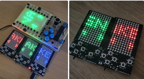
Step 1: The Screen


The impressive screen of 160 LEDs from Wurth Elektronik is arranged in a matrix, controlled by 20 output pins on the PIC18F4550 microcontroller. These LEDs can be chosen from a range of optoelectronic components and colors, allowing for customization and flexibility in the display.
We employ typical NPN transistors to switch between the rows and columns of LEDs. To optimize control and minimize the number of IO pins used, we have divided the screen into four sections. The screen’s refresh cycle operates at one row every 2 milliseconds, resulting in a complete screen refresh rate of 32 milliseconds. This gives us an overall refresh rate of 31.25 Hz, which is more than sufficient for the games we plan to program.
Step 2: The BMS

The BMS can be divided in three parts:
- TP4056: The famous chip that will charge any Li-Ion battery from the USB port of the device.
- AP9214L: It is the battery protection IC. It will disconnect the battery in case of undervoltage, overcharge voltage, overcurrent… and so much more.
- TPS61085T: It is the boost converter that level up the voltage from the battery to a stable 5V for the microchip and the electronics.
Step 3: The Main Chip

The circuit is built around the PIC18F4550, an 8-bit microcontroller featuring a 32KB program memory size and 2048 bytes of RAM. Additionally, it includes 256 bytes of EEPROM, which is perfect for storing the scoreboard and various settings.
Despite the small amount of memory available, the IC has 13 ADC channels with a resolution of 10bits (which will be used to identify the battery voltage), it operates up to 5.5V, and the pin count increases up to 40 IO, which are extensively used to control the screen, read the buttons and make some music with the buzzer.
Step 4: The PCB Design


2 More Images
The PCB is a four layer PCB made by PCBWAY. Remember you have the gerber and all the files in the github repository!
https://github.com/makingdevices/PicBytesMicro/tree/main/Gerber
Step 5: Soldering the Chip


I strongly recommend to buy a stencil to spread the solder paste.
In my case, I soldered all the smd components (The top layer first, indeed) so I was able to use a reflow heatplate for the 160 LEDs of the screen.
Once all the SMD components are soldered, I started soldering the TH components. Last but not least, solder the battery.
Step 6: Software and Burn the Chip


You will need a Tag-Connect 6-pins cable for the ICSP on the board. You will find the code here:
Or from the attached file. You should use MPLAB and C18++
The code is available at:
Step 7: Final Result

In the video you will see the different versions:
- Prototype: Fully operational. I almost gave up when soldering everything by hand, more than 40h (probably more!) to have the first version assembled.
- V1: The programming pins of the PIC18F4550 were not in position. There also wasn’t a battery protection IC.
- V1.2: Everything was working BUT one button! dammit :/
- V1.25: Everything was working PLUS I added a battery voltage detector using the ADC of the PIC, and now I can control the state of the battery.
Everything you see here is Open Source, and the project is OSHWA certified: ES000047
Step 8: Links and Sponsors


