

This is a tutorial showing you how to make your own Arduino GPS module that you can use to measure the maximum speed and average speed of a moving object. I created this project because I was curious how fast my RC planes went and thought it would be a good simple project to test out my coding and building skills.
It is possible to make my final module give more data than just speed, such as altitude, and coordinates. This could easily be done with abit of tinkering in my code.
It is also possible to connect your module to give live telemetry data to an RC plane receiver however I decided to make a more basic one which can be used over many different types and brands of receivers. If you would like to do this I would recommend you to do further research into your own receiver.
Supplies
For this project I have used:
1 x Arduino nano (any Arduino board will be fine)
1 x Ublox Neo 6m GPS module (any RX/TX GPS that is compatible with Arduino will be fine)
1 x Tactile switch (any momentary switch will be fine)
Servo wire and similar small gauge wire
It is also possible to use an SD card and card reader for storing data however due to the size constraints of my project I have opted not to do this.
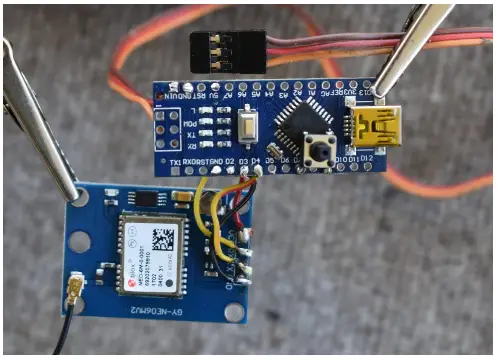
Step 1: Wiring
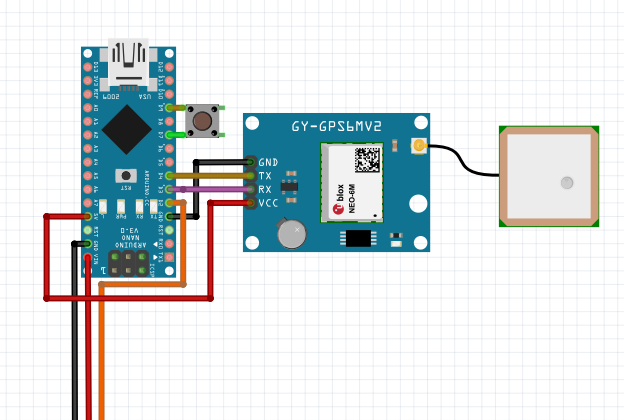


For this step, we have to solder the GPS device to our Arduino:
- The TX Pin of the GPS can be connected to any digital pin however I have connected it to digital pin 4.
If you do decide to change the TX or RX pin numbers just remember to change them in the code as well.
- Similarly, the RX pin can be connected to any digital pin. I have connected it to digital 3.
I have made this module so that it doesn’t need this pin to operate thus it is not crucial however it can be useful in the future if you wish to have more functionality with your GPS device. It should be noted that many GPS’s can only have 3.3v supplied to this pin so a logic level converter or voltage converter may be required for this functionality.
- The Vcc of the GPS (Voltage in) is connected to my 5v power supply on the Arduino however your GPS may require 5v or 3.3v input so connect this pin to the suitable one on the Arduino.
- The ground pin of the GPS can be connected to any ground port of the Arduino.
Soldering the servo cable to the Arduino:
- The ground (usually black or brown) can be connected to any ground pin on the Arduino.
- The live wire (usually red or the middle cable) supplies power to the Arduino therefore it should be connected to the Vin pin on the Arduino.
- The signal wire (usually white or yellow/orange) is optional, and I connected this cable to digital 2 on my Arduino.
This cable is required for transferring live data between the Arduino and the receiver however if you opt to do this it must be connected to a suitable port on the receiver and usually cannot be connected to the standard PMW output ports. This may require a different connect on the end than the male servo pin I have.
Soldering the switch:
- The switch can be soldered to any 2 remaining digital pins on the Arduino. I have soldered mine to digital 7 and 9. The switch only has to transmit a High or Low signal to the Arduino when it is pressed.
I would use a multimeter to double check that the 2 pins you are soldering to the Arduino only connect when the switch is pressed. If you use different pins than I have used you will have to update the code so it works with the switch on the different pins.
In my pictures of my GPS module all of the cables and switch are compact, this is due to the limited size of the RC plane which I want it to go in, you don’t have to make the cables this size however it will be easier to print a case and make your module small. Now that everything is soldered, we can move onto the next step:
Step 2: Testing (optional)
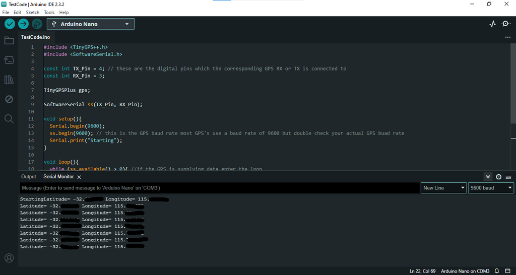
Now that everything is soldered and ready to go, we can double check that it is working properly by uploading a simple code, when running this code on the Arduino it is important to make sure you are outside to get a better GPS fix. You might also have to wait a little while for the GPS to lock on and start receiving data:
(This code assumes that the TinyGPSPlus library is installed. It can be installed by going to Tools in the top left corner than Manage Libraries in the pop down menu than by searching TinyGPSPlus into the search bar and clicking install)
The following is a short code inspired by Rui Santos from Guide to NEO-6M GPS Module Arduino | Random Nerd Tutorials
#include <TinyGPS++.h>
#include <SoftwareSerial.h>

const int TX_Pin = 4; // these are the digital pins which the corresponding GPS RX or TX is connected to
const int RX_Pin = 3;

TinyGPSPlus gps;

SoftwareSerial ss(TX_Pin, RX_Pin);

void setup(){
  Serial.begin(9600);
  ss.begin(9600); // this is the GPS baud rate most GPS's use a baud rate of 9600 but double check your actual GPS buad rate
  Serial.print("Starting");
}

void loop(){
  while (ss.available() > 0){ //if the GPS is supplying data enter the loop
  gps.encode(ss.read());
  if (gps.location.isUpdated()){ //if the supplied data is updated proceed to the next step
    Serial.print("Latitude= ");
    Serial.print(gps.location.lat(), 6); //reads and prints the data
    Serial.print(" Longitude= ");
    Serial.println(gps.location.lng(), 6); //reads and prints the data
  }
  }
}
Once this code is running you can open serial monitor and should start seeing values printing. If values are not printing than your GPS might not have been wired correctly and you might have to go back to step 1 or it has not gotten a GPS fix.
You can double check that the values you receive are accurate by putting them into google earth. If your readings are a bit inaccurate it is likely because the GPS is in close proximity to a computer, which creates a lot of noise interfering with the GPS signal.
Attachments
Step 3: Downloading the Code
Once you have tested your GPS and it is working correctly it is now time to download the main code onto the Arduino. I have created the following code to use. This code finds the running average of the speeds to calculate the maximum speed reached and the average speed.
I use a running average because when the RF system of the receiver is activated it can cause the GPS readings to jump around a bit, the running average helps to minimize these bumps for a more accurate reading at the cost of responsiveness. You can change the number of averages to make it more accurate (increase it) or more responsive (decrease it) I currently have it set to 3.
This code can be changed to give you speed in miles per hour, meters a second, knots and kilometers an hour. You can also later add altitude (calculated from the GPS) or other settings, the following link displays a lot of useful information; Guide to NEO-6M GPS Module Arduino | Random Nerd Tutorials
Another important thing to note is that the data storage (EEPROM) can only write and erase data 100,000 times. I have made my code only store data into the Arduino’s EEPROM at the end of a flight so this value shouldn’t be reached, but if you needed to store this much data a better alternative would be an SD card connected to the GPS module.
#include <TinyGPS++.h>
#include <SoftwareSerial.h>
#include <EEPROM.h>


// ====================================== GPS Values ===========================================


static const int TX_Pin = 4, RX_Pin = 3;  // these are the pins which the rx and tx of the gps are connected to. the tx pin of the gps is the most imprtant one and that pin number is used for the TX_Pin value (ie: tx to digital 4 means TX_Pin = 4)
static const uint32_t GPSBaud = 9600;     //this is the baud rate of the gps, this should apply to your gps but you might need to check the data sheet.


// ====================================== Moving Averge Values ===========================================


const int numReadings = 3;        // Number of readings for the running average 3 is a good balance between responsiveness and accuracy
float readings[numReadings];
int readIndex = 0;
float total = 0, MovingAverage = 0;


// ====================================== Speed Values ===========================================


float speed, speed2, maxSpeed, aveSpeed, sumSpeed = 0;


volatile int speedCount = 0;


// ====================================== Switch ===========================================


const int inputPin = 9;  // Pin connected to one side of the swicth
const int outputPin = 7;  // Pin connected to the other side of the switch


bool done, programingMode = false;


// ====================================== Setting up the gps serial ===========================================


TinyGPSPlus gps;                  //Creates a gps device for the TinyGPS+ library


SoftwareSerial ss(TX_Pin, RX_Pin);  //Connects the serial of the gps to get data


// ====================================== Setting up the code ===========================================


void setup() {
  Serial.begin(9600);           // Initialize serial communication with the computer if it is connected
  ss.begin(GPSBaud);            // Initialize serial communication with the gps if it is connected


  for (int i = 0; i < numReadings; i++) { // Initializes all moving average values to zero
    readings[i] = 0;
  }


  pinMode(inputPin, INPUT_PULLUP);    //sets up the switch pins ready to collect data
  pinMode(outputPin, OUTPUT);
  digitalWrite(outputPin, LOW); // make one pin of the switch high


  pinMode(LED_BUILTIN, OUTPUT);
  digitalWrite(LED_BUILTIN, HIGH);


  delay(1500);


  digitalWrite(LED_BUILTIN, LOW);


  delay(500); // allows 2 seconds before you cannot access programming mode


  if ((digitalRead(inputPin)) == LOW){ //activates prgramming mode
    programingMode = true;
    done = true;
  }
}


void loop() {


  if (((digitalRead(inputPin)) == HIGH) && (done == false)) { //if the switch has not be activated and the code is not finished it will gather data


    digitalWrite(LED_BUILTIN, LOW);


    // ====================================== Gathers Data ===========================================


    while (ss.available() > 0){       // if the gps is available it eneters a loop to collect data
      gps.encode(ss.read());          //Reads data
      if (gps.location.isUpdated()){  //If the data has been updated it proceeds to the next stage
        speed = gps.speed.kmph();     //Gets and calculates the speed value from the gps. Instead of .kmph() it could be .knots() or .mph() or .mps() depending on what units you want
      }
    }


    // ====================================== Begins Calculations ===========================================


    if (speed != speed2){     // if the speed value from the gps has changed
      speed2 = speed;         // sets current speed as previous speed


      digitalWrite(LED_BUILTIN, HIGH);


      // ====================================== Moving Average Calcualtion ===========================================


      total = total - readings[readIndex];     // Subtract the last reading
      readings[readIndex] = speed;             // Sets the value to be averaged as the current speed value
      total = total + readings[readIndex];     // Add the reading to the total
      readIndex = readIndex + 1;               // Advance to the next position


      if (readIndex >= numReadings) {          // Wrap around when reaching the end of the array
        readIndex = 0;
      }


      MovingAverage = total / numReadings;     // Calculate the Moving average


      // ====================================== Other speed calculations ===========================================


      if (MovingAverage >= maxSpeed){       // if the Moving Average speed is larger than the maximum speed found previously the maximum speed is updated
        maxSpeed = MovingAverage;
      }


      sumSpeed = sumSpeed + MovingAverage;  // Calulates the total average using the moving average speed.
      speedCount = speedCount + 1;
      aveSpeed = (sumSpeed/speedCount);
    }


  } else if (done == false) { // if the switch is clicked and the code is not finished


  digitalWrite(LED_BUILTIN, HIGH);


  delay(500);


  digitalWrite(LED_BUILTIN, LOW);


  // ====================================== EEPROM ===========================================


    for (int i = 0 ; i < EEPROM.length() ; i++) { //clears eeprom memory
      EEPROM.write(i, 0);
    }


    EEPROM.put(0, maxSpeed); //writes the float values to the EEPROM memory
    EEPROM.put(5, aveSpeed);


    done = true; // code is now finished


    digitalWrite(LED_BUILTIN, HIGH);


  } else if (programingMode == true) { //if the switch was depressed when powering on


    digitalWrite(LED_BUILTIN, HIGH);


  // ====================================== Waiting for Computer signal ===========================================
  while (Serial.available() <= 0){
    Serial.println("Type Aything to Receive Data");
    delay(3500);
  }


  // ====================================== Recieveing stored data ===========================================


    Serial.println("");
    Serial.println("Programing Mode");
    Serial.println("");


    delay(1000);


    Serial.println("Maximum Speed Reached: ");
    EEPROM.get(0, maxSpeed); //gathers data from the stored memory
    Serial.print(maxSpeed); //prints the data
    Serial.println(" km/h");


    Serial.println("Average Speed: ");
    EEPROM.get(5, aveSpeed); //gathers data from the stored memory
    Serial.print(aveSpeed); //gathers data from the stored memory
    Serial.println(" km/h");


    programingMode = false; //Code is finished and programming mode is off
    done = true;
  }
}
Attachments
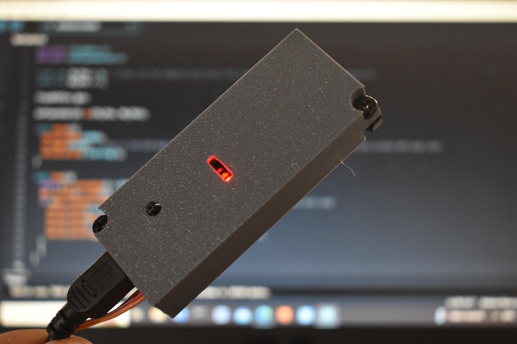
Step 4: Using the GPS Module


The image above shows the main things we will use, number 1 is the tactile switch, number 2 is the power LED this is always on and should be ignored, the third one is the Arduinos built in LED which is programmed to turn on and off as seen below:
initialization:
Plug the Arduino into the RC Plane receiver and power it up. When powered up the Arduinos built in LED (the one with L written next to it) will light flash for a bit then light up once more and go out. This happens every time it is powered up and indicates the Arduino has initialized and is ready to record data.
Data collection (inflight):
When nothing is pressed the light should start faintly blinking this indicates that the Arduino is receiving data from the GPS module. When flying your plane, the Arduino will automatically receive and interpret data from the GPS and note down the maximum speed and the average speed.
- If the light is not blinking it means that no data is being collected from the GPS. If this is the case it could be from the GPS not having a satellite fix which means you may just have to wait a couple of minutes, or it could be because the RX and TX pins in the code we incorrectly defined.
Saving Data
Once you finish flying don’t power down the receiver, instead tap the button which is connected to the Arduino. When this happens, the LED should light up for half a second, then go out. When the light turns on again and stays on, it indicates that the data has been successfully saved to the Arduinos memory. Don’t power off the Arduino until this happens and the LED becomes a solid light for more than a second. after this has happened it is now safe to power down and remove the Arduino from the plane’s receiver.
Getting the Data:
Now that you have removed the Arduino from the plane prepare to plug it into the computer. Open the Arduino IDE on your computer. Press and hold the tactile switch when you plug in the Arduino module into your computer. Continue holding the tactile switch while you open the serial monitor on your screen (to open serial monitor go to Tools and select Serial Monitor in the drop-down menu) Continue to hold the switch until you receive this message from the Arduino:
‘Type Anything to Receive Data’
Type anything into the bar in the serial monitor (the one which says type message to Arduino) and press enter. The following message as well as your flight data should appear:
‘Programming Mode’
It is important to note that you cannot power the Arduino from anything if you want to connect it to the computer, thus you must make sure it is disconnected from the receiver before you retrieve any data.
- If you are not getting any data or message, make sure the right board is connected in the top left corner of the screen.
- If you get a bunch of wired letter things make sure the baud rate of the serial monitor is set to 9600.
- When doing this step, you might have released the button too soon or didn’t push it in time to initialize the programming mode. This is alright, just remove the Arduino from the computer and try again. As long as you don’t tap the button after it has initialized the stored data will not change.
- If you only receive 0’s, it is likely because the GPS module did not have a fix while it was powered on.
Your GPS module is now ready to go back into the RC Plane and this process must be repeated to get additional data.
If the GPS loses a satellite fix while it is in your plane this will not affect your final data results.
Step 5: Making a Case


I quickly designed a nice simple case in fusion 360 to 3d print for my Arduino and GPS. If you do not have a 3d printer you could use large heat shrink or even tape as long as everything is held together and doesn’t rattle around. Just be careful with the GPS antenna because most of them are liable to fall off if not properly secured to the GPS. I also recommend having the Arduino’s built in LED visible so that it makes it easier to see what you are doing.
When making the case make sure that you can see the Arduinos built in LED, you can tap the switch and you can plug a cable into the Arduinos programming port.
I have included the stl files for my case, keep in mind that it is very compact and uses some small m4 bolts which I had lying around.
Attachments
Step 6: Installing the GPS Module
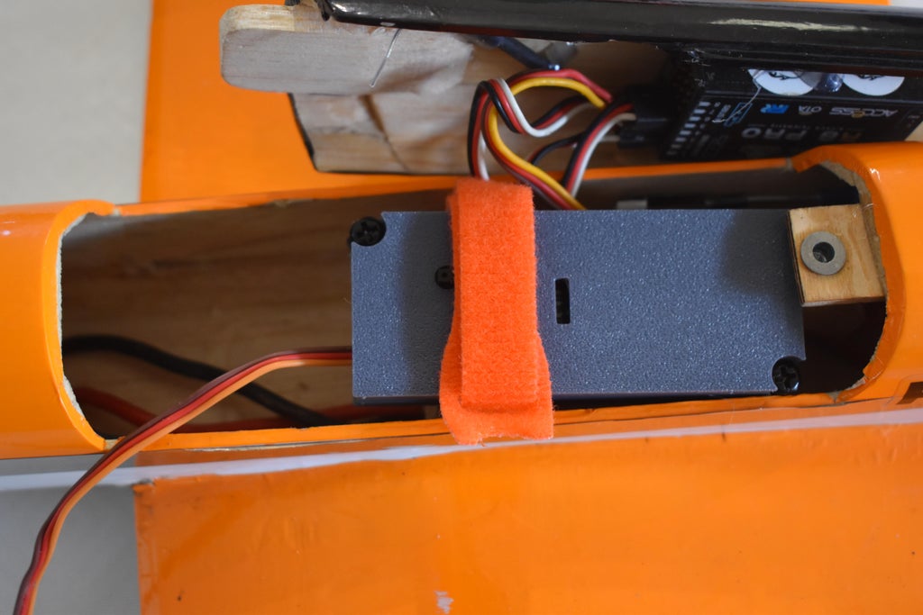
When installing the GPS module into your RC plane I would recommend putting foam between it and any points of contact however this is not necessary for electric models, I would also recommend having your GPS antenna facing upwards and as far away from the receiver as possible in order to get the best signal. It would also make it easier to use if the lights, switch and button are easy to see and reach. Finally, it would probably be easier to use if the GPS module was easily removable from the RC plane.
For these reasons I recommend using Velcro or Velcro straps to attach the GPS module to the RC plane. This may require you to hot glue one side of the Velcro to the plane and the other to the GPS module.


