
By UDEMIE, Circuits > Arduino


Hey everyone! I’m excited to share what I believe is one of the most practical and valuable instructables I’ve published. You might be wondering why I think so, and I’m here to explain.
Imagine you’ve been cooking in the kitchen, and at least once, you’ve encountered this situation: forgetting to turn off the gas. Alternatively, there are those times when the flame is extinguished due to food or liquid spilling over the burner. Both scenarios lead to a common and dangerous result: gas leakage.
Just to clarify, when I refer to gas, I’m talking about LPG (liquefied petroleum gas), not petrol, as the term “gas” can mean different things in different regions.
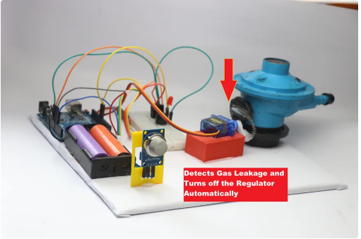
LPG leakage poses significant hazards, and in this instructable, I’ll show you a way to automatically turn off the gas regulator when a leak is detected and alert you simultaneously. Isn’t that amazing?
I’ll provide a high-level overview, and for more detailed information, you can follow the steps in my instructable.
We will use the MQ2 sensor, which detects LPG, methane, and smoke, to trigger a servo that controls the gas regulator. I’ve designed this system to be simple enough for anyone to build and use. Below, you’ll find the circuit diagram, explanations, and the Arduino program needed to create this gas leakage detection system.
By following this guide, you can enhance kitchen safety and prevent potentially dangerous situations caused by gas leaks. This system not only provides peace of mind but also adds an extra layer of security to your home. So let’s get started, and I’ll walk you through every step to build and implement this life-saving device.
Supplies
Components Needed for the Gas Leakage Detection Project
To build this gas leakage detection system, you’ll need the following components:
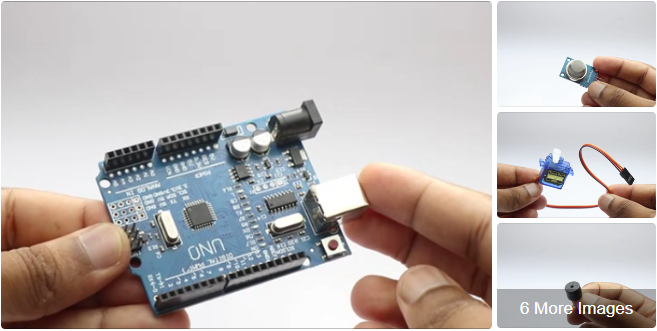
- Arduino Uno Board
- This microcontroller will be the brain of our system, processing the data from the gas sensor and controlling the servo motor.
- MQ2 Gas Sensor
- This sensor is capable of detecting LPG, methane, and smoke. It will trigger the system to take action when it detects gas leakage.
- Small Buzzer
- The buzzer will sound an alert when gas leakage is detected, providing an audible warning.
- LED
- An LED will serve as a visual indicator, lighting up when the system is activated or when gas is detected.
- Old Regulator
- This will be modified and integrated with the servo motor to automatically turn off the gas supply when a leak is detected.
- 18650 Battery with Holder and Switch
- This battery will power the entire system. The holder and switch make it easy to replace the battery and turn the system on and off.
- Servo Motor / Micro Servo
- The servo motor will control the regulator, turning it off when the MQ2 sensor detects gas.
- Jumper Wires
- These wires will be used to connect the various components to the Arduino board.
- Breadboard (Optional)
- A breadboard can be used for prototyping and testing the circuit before making permanent connections.
- Piece of Cardboard
- The cardboard will be used to mount and organize the components.
- Hot Glue
- Hot glue will secure the components in place on the cardboard.
- Arduino IDE and Programming Cable
- The Arduino Integrated Development Environment (IDE) and a programming cable will be used to write and upload the code to the Arduino Uno board.
Note: The links provided for these components are Amazon affiliate links. I may receive a small percentage on qualifying sales at no extra cost to you. This support helps me create more great project ideas like this one.
By gathering these components, you’ll have everything you need to build a functional gas leakage detection system that enhances the safety of your kitchen. Let’s dive into the construction and programming process to bring this project to life!
Step 1: Circuit and Program
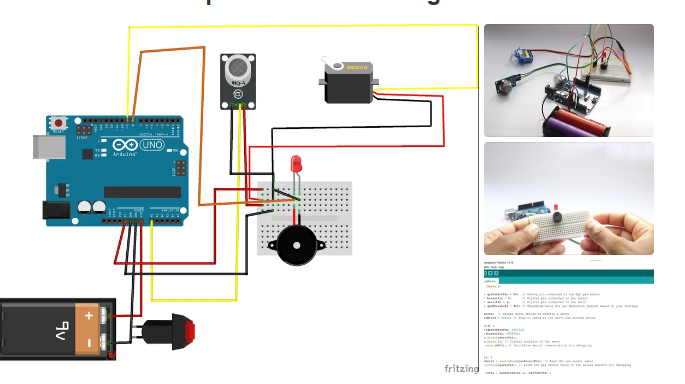
The first step is building the circuit after you have all the components ready if you are new to this don’t worry here is the Circuit explanation for those who have trouble understanding the diagram, The project has 3 main components, MQ2 sensor, Servo and buzzer(With Led)
MQ2 Gas Sensor connections
VCC pin is Connected to 5V on the Arduino
GND pin is Connect to GND on the Arduino
AO (Analog Output): Connect to analog pin A0 on the Arduino.
Buzzer
Positive which is longer leg is connect to digital pin 8 on the Arduino
Negative (shorter leg) is connected to GND on the Arduino
Servo Motor Connection
Red Wire to 5V on the Arduino
Brown Wire to GND on the Arduino
Orange Wire to digital pin 9 on the Arduino
After you have connected all these components together we can head over to uploading the code to Uno.
Simply copy and paste the below code to your IDE, select proper port number and click on upload and you should see the code uploading without any issues.
Step 2: Circuit Setup
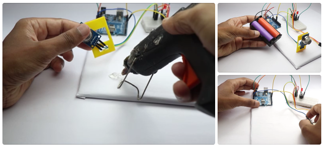
Once all the components are properly interconnected, the next step involves securely mounting them onto a sturdy piece of cardboard. In my project, I opted to use custom 3D-printed parts designed specifically to house and stabilize the gas sensor and servo motor, ensuring they were securely positioned and aligned correctly.
For those without access to 3D printing capabilities, an alternative approach involves cutting out cardboard pieces shaped to accommodate the sensors and other components. It’s essential to apply a generous amount of hot glue during assembly to firmly anchor each component to the cardboard base, ensuring stability and reliability.
To begin, I initially used double-sided adhesive tape to affix the nano-controller in place, then proceeded to carefully glue down the gas sensor, breadboard, and gas regulator. Given the presence of moving parts such as the servo motor, it’s crucial to ensure they are firmly secured to prevent any unintended movement or vibration during operation.
It’s worth noting that there are multiple ways to configure this setup according to specific project requirements. Based on my own experience and needs, I found this method to be highly effective and reliable for ensuring the components remain securely in place during use.
Step 3: Regulator On/off Mechanism

The most important part of this project is this on and off mechanism, i tried many ways but in the end i found that using spring has many advantages.
The number one advantage is the shocks, the servo and the regulator switch movements are slightly different and if you are thinking to glue the horns of servo directly the servo wont be able to function well.
So i used spring and this also minimises the shock, glue the spring to the regulator switch and allow to dry completely followed by gluing the end of the spring to the servo horns.
Make sure you have sufficient distance for the swing movement in the switch and no obstacles are on the way during its action.
Before gluing turn on the project check for the position of the servo horn, after the gas regulator switch is turned to off by the servo to reset the device you have to manually turn on the regulator and all thanks to the spring to provide this flexibility
Step 4: How to Use


….
This is very easy! All you have to do is connect this setup to the regulator and make sure that the regulator switch is aligned well with the horns of the servo.
To take the best advantage of this setup make sure that the gas sensor has elongated wires and the sensor is placed near the burner(take care of the heat part!)
Now when you power on the setup the servo returns to its original position(when the regulator switch is On now adjust the regulator position and leave the rest to this setup!.
In case if you forget to turn of the gas or in some case due to spillage of the food on the burner the fire on the gas goes off so now the leakage of gas happens at this moment the mq2 picks up the gas.
It alerts you with the sound of buzzer along with red light and instantly the servo horn moves thereby turning off the regulator switch.
to reset the system all you have to do is manually turn on the regulator switch along with servo horn and now turn on the power and the system is ready for use now.
This is all about this project if you have any suggestion for improvements let me know in the comments, Thanks and happy building.