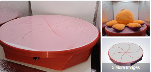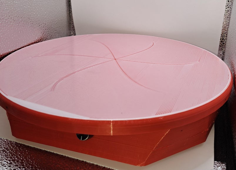
For the past three years, I’ve been immersed in 3D printing and modeling STL parts. This journey naturally led me to explore product photography, albeit somewhat unexpectedly and voluntarily, hehehe…
I’ve always admired the dynamic, animated images used to showcase figures, parts, and projects, and I aspired to create my own professional .gif images. During my online quest for “how to create my own .gif,” I found numerous guides and tutorials. My initial attempts were successful, but I encountered a recurring issue: how to efficiently rotate and capture professional photos of my creations?
Further research led me to manual turntable solutions that required manual rotation, which seemed far from an ideal solution. I was convinced there had to be a more professional and autonomous way to achieve this, particularly using an ESP32-based project due to its Bluetooth connectivity capabilities.
While I discovered some similar solutions, none offered an integrated autonomous turning mechanism combined with photo capture. Thus, I decided to create my own solution. Now, I am thrilled to present my autonomous “Turning Turntable.”
This innovative turntable autonomously rotates and captures images of an object from various angles. The number of photos can be parametrically adjusted to capture up to 64 images of the object. Finally, the images can be merged into a .gif using either a computer or even your smartphone.
Supplies
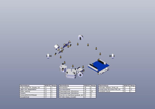
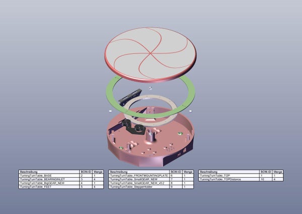
For this project, a solid understanding of electronic devices and adeptness in working with 3D-printed parts, along with components like screws and heat inserts, is essential.
To assist with the setup, I’ve provided an overview of the necessary parts. Please also refer to the images above, which include the assembly view and the bill of materials (BOM) for both the self-made 3D-printed parts and the purchased components. The total cost is approximately €70, though this can vary depending on where you source the components and what you already have on hand.
- ESP32-Arduino-Fake Board: Amazon / AliExpress
Using an Arduino Footprint based ESP32 Board, because of the onboard available Power Input possibilities.
- Arduino-Prototyping Shield: Amazon / AliExpress
In Theory, you can use any Pototyping Shield. I used this one with screw Terminals to secure everything in place.
- Stepper-Motor:
During my comissioning I was not happy with the max. velocity of the turntable by using this stepper motor: Amazon / AliExpress.
You can actually use it together with a ULN2003 or LD293(Motor in Bipolar Mode!!!) driving stage and it actually will work in a really slow speed. The Software/Hardware part can be setup/parametrize for it easily, but i will not recommend it!
For a much more better result i used the following Pancake NEMA 17 Stepper Motor: Amazon / AliExpress This stepper has much more torque and can turn the turntable with a good speed if a good stepper driver is used.
- Stepper-Motor Driver: (See Stepper-Motor)
Driver Stage between the Stepper and the ESP32. You can use like mentioned above the kit or an LD293 if you adjust the Motorcoils for Bipolar mode Amazon / AliExpress for the 28byj-48 stepper motor. To Operate the NEMA 17 pancake stepper, i would suggest you to use an better stepper driver with microstep operation. I finally used the following PCB Breakout Amazon / AliExpress
- Rotary Encoder: Amazon / AliExpress
Encoder for the Display usage.
- 1,3” OELD Display: Amazon / AliExpress
In Theory, you can use any display you want! If you have a different one you will have to adjust the cut-out of the 3D-print and do some adjustements in Sourcecode. If you need help – you can contact me.
- Ball-Bearings: Amazon / AliExpress
Ball-Bearings are used to support the turning movement of the Turntable. You will need at least 4pcs.
- Power Supply: Amazon / AliExpress
I recommend using an external minimum 12V/2A Power Supply to operate the Project. You can use one with On-Board Power-Switch to turn On/Off the Turntable.
- M3/M4 Heat Inserts: Amazon / AliExpress
You will need 16x M3x3mmx5mm Heat Inserts and 2x M4x4mmx6mm Heat Inserts and I would recommend you, to order a whole sortiments box which includes all different kinds of Heat Inserts you will need.
- M3/M4 Screws: Amazon / AliExpress
The same is with the Screws! I will recommend you to order a whole Sortiment with Screws, Nuts and Washers.
- Cables & Connectors: Amazon / AliExpress
Various cables for wiring and Connectors are needed to connect the Electrical Components together. I have a lot of these things laying around. Therefore I picked out a link to a sortiment where Anything should be togehter, you will need to complete this project.
You will also need the following Tools/Setup:
- 3D-Printer
- PC with Visual Studio Code & Platformio
- PC with Slicing Software
- Depending on your personal Setup: Soldering Iron and Solder (If you only have ScrewTerminals and Dupont wires i think it is not necessary)
You will also need some wires for connecting the electronic devices together. Depending on the shield you are want to use, you can use just jumper-dupont wires or making some custom cables.
For the 3D-print of the parts, I suggest to use default PLA for the mechanical parts. I also designed some parts in TPU to add some damping on e.g. the feets of the base-part.
Step 1: Preperation: 3D-Print
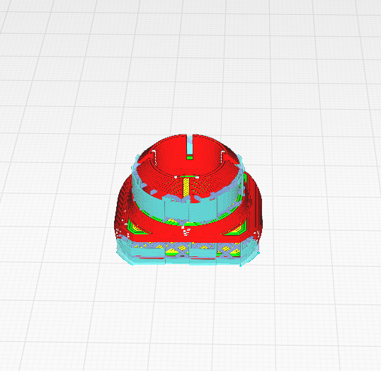
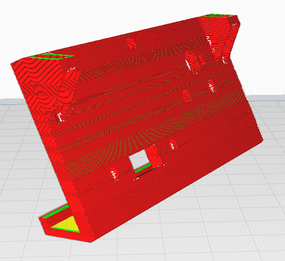
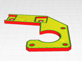
Before starting the Turning-Turntable project, ensure you have access to a 3D printer to produce the necessary parts. The base and top parts are designed for a 0.6mm nozzle, while all other parts are optimized for a 0.4mm nozzle. However, it is theoretically possible to print everything with a 0.4mm nozzle.
Begin by downloading the STL file for the turntable from Cults3D and proceed to print it using your 3D printer. Follow the instructions provided in the download link on Cults3D. Be sure to use the promo code “TURNTABLE4EVER” to receive a 20% discount off the original price.
I printed the feet, bearing inlets, and top spacers using TPU, while all other parts were printed with standard PLA. The base part and legs require support for optimal printing quality, whereas all other parts do not need support. For further guidance on printing orientations, refer to the pictures included in this step. I’ve added my printing orientation for each part to provide a clearer overview.
Step 2: Assembly the Turntable Base Part – Heatinserts
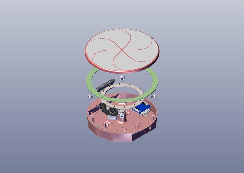
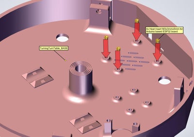
In this step, the turntable base part is prepared for the subsequent assembly stages. Begin by inserting a total of ten M3x3x5 heat inserts to secure the Arduino board, stepper motor driver board, and front frame. Next, install two M4x5x6 heat inserts for the stepper motor or, depending on your setup, for the additional stepper motor holder.
Step 3: Assembly the Turntable Base Part – Installation of the Bearings
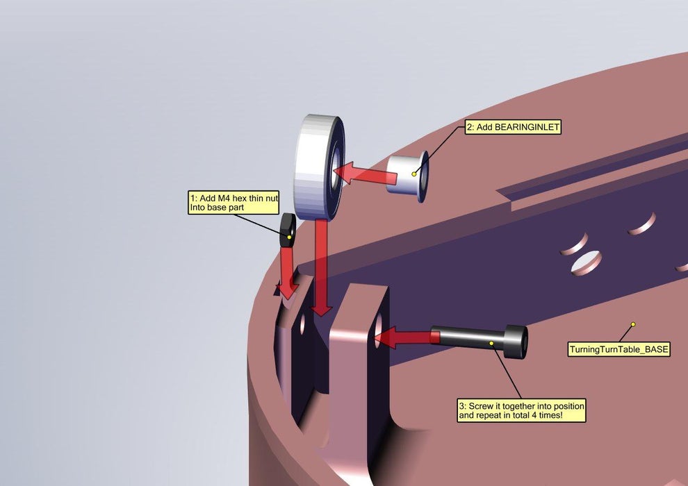
In this step, the bearings are installed within the turntable base. These bearings help reduce friction when additional weight is placed on the turntable. Begin by placing a hex nut into the groove of the base part. Next, mount the 3D-printed bearing inlets and secure them with an M4 screw to hold them in place. Repeat this process a total of four times.
Step 4: Assembly and Mount of the Display Frame Within the Turntable Base Part
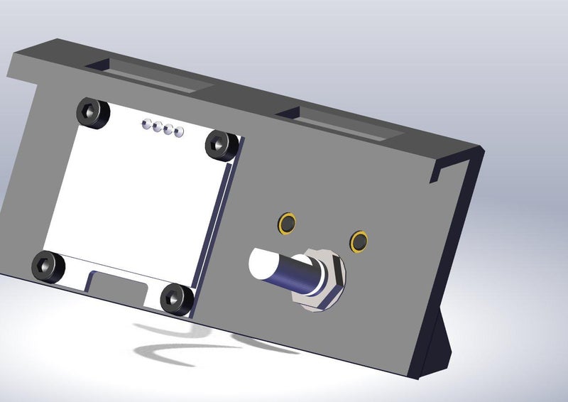
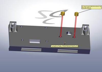
In this step, the display frame will be assembled. You will need the 3D-printed turntable front part, the OLED display, and the encoder. To secure these components together, you can install six M3x3x5 heat inserts, as the parts were designed for this purpose.
For my prototype, I used only M3 screws, washers, and nuts to hold the parts in place. This method works perfectly, and the screws do not interfere with the inside of the turning turntable.
Start by inserting the encoder and securing it with the provided hex nut and washer on the outside of the front display frame. Then, screw the M3 screws from the front side through the part and secure them. Next, place the OLED display and secure it with four M3 screws and optional nuts.
Once the front display is fully assembled, snap the turntable front part into the turntable base and secure it with two M3 screws. Finally, mount the encoder knob from the outside of the assembly.
Step 5: Assembly the Turntable Base Part – Installation of Stepper Motor
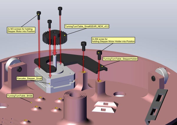
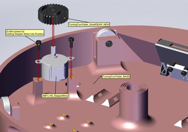
In this step, you can now mount the stepper motor with the small gear.
The small gear can be pressed directly onto the motor shaft. If you are using the NEMA 17 Pancake Stepper, there is a prepared hole on the flat part of the shaft where an M2 heat insert with an M2 screw can be added to secure it in place. However, I found the fit to be tight enough on the shaft that additional securing was unnecessary.
Depending on the selected stepper motor, there are two mounting instructions for the turntable base:
- If using the 28byj-48 stepper motor, it can be screwed directly into the M4 heat inserts with two M4 screws without any further adjustments.
- If using the 17HS08 Pancake NEMA 17 stepper motor, first mount the adapter plate to the stepper motor using three M3 screws. Then, mount the adapter to the original 28byj-48 mounting positions using two M4 screws.
Step 6: Assembly the Turntable Top Part – Heatinserts
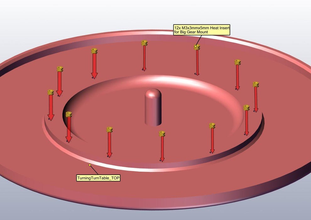
To mount the large gear of the turntable onto the top part, begin by inserting sixteen M3x4x5 heat inserts into the 3D-printed component.
Step 7: Assembly the Turntable Top Part – Mounting the Big Top Gear
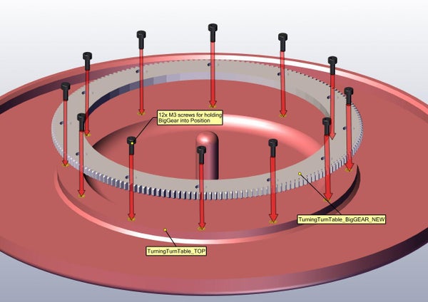
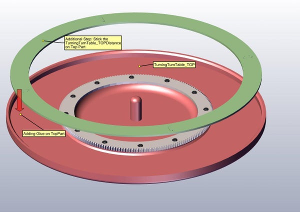
With the heat inserts installed, you can now mount the large gear onto the top part of the turntable using M3 screws. Additionally, you have the option to add TPU spacers on the top part of the turntable. These spacers will ensure smoother operation during rotation. Simply use plastic glue to affix the spacers into place.
Step 8: Adding Electronic – Hardware
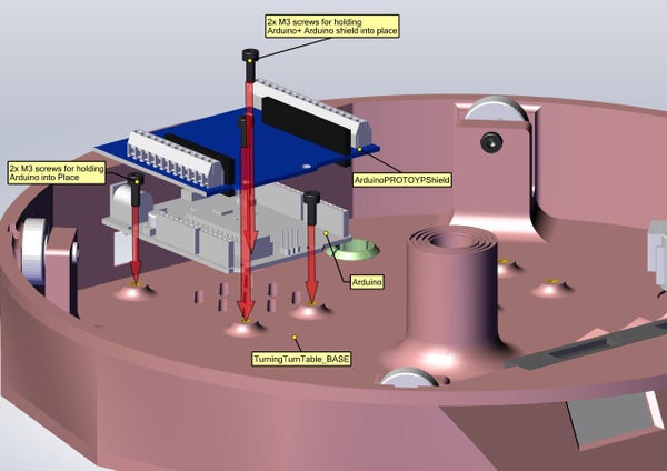
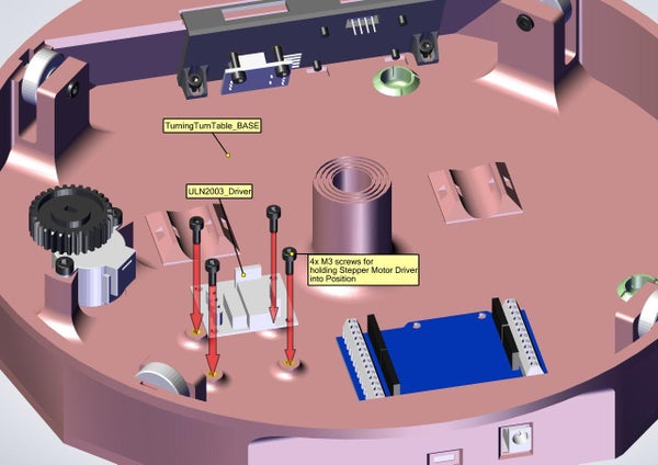
In this step, we begin by mounting the chosen stepper driver PCB in place using 4x M3 screws. Depending on the stepper motor driver used, I made adjustments during my build. The original mounting holes are designed for the ULN2003 driver. However, they do not align perfectly for the LD293 stepper motor driver board, which fits well using only two of the four holes.
Next, place the Arduino-style ESP32 board (without the shield) and secure it with 2x M3 screws diagonally. Then, attach the shield to the Arduino board and secure it with longer M3 screws through the remaining holes, passing through both the ESP32 and Arduino boards to secure the shield and base board firmly in place.
Step 9: Electrical Wiring
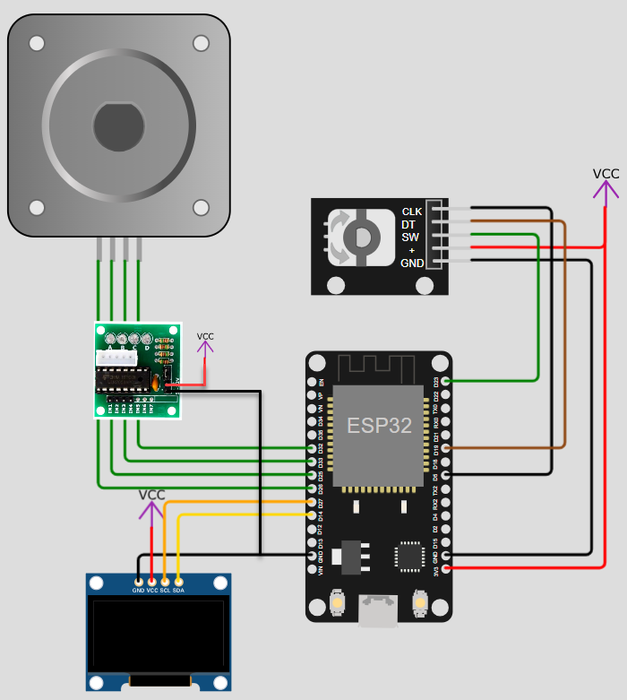
In this step, all components are wired together. I’ve used handmade custom DUPONT connectors for the encoder, OLED display, and stepper motor driver. When wiring the stepper motor and driver, it’s crucial to match the stepper type and selected driver with the corresponding pin setup in the source code. Pay close attention to the supply voltage for the stepper motor driver board.
For instance, since I’m using the 17HS08 stepper motor with an A4988 driver, I directly supply the driver board via the VIN pin on the ESP32-Arduino board, which is powered by a 12V adapter. If you’re using the 28byj-48 stepper motor with a ULN2003A driver, do not connect it to 12V! Instead, connect it only to a 5V external power supply or the 5V pin on the ESP32-Arduino board.
Step 10: Assembly the Turntable Base – Legs
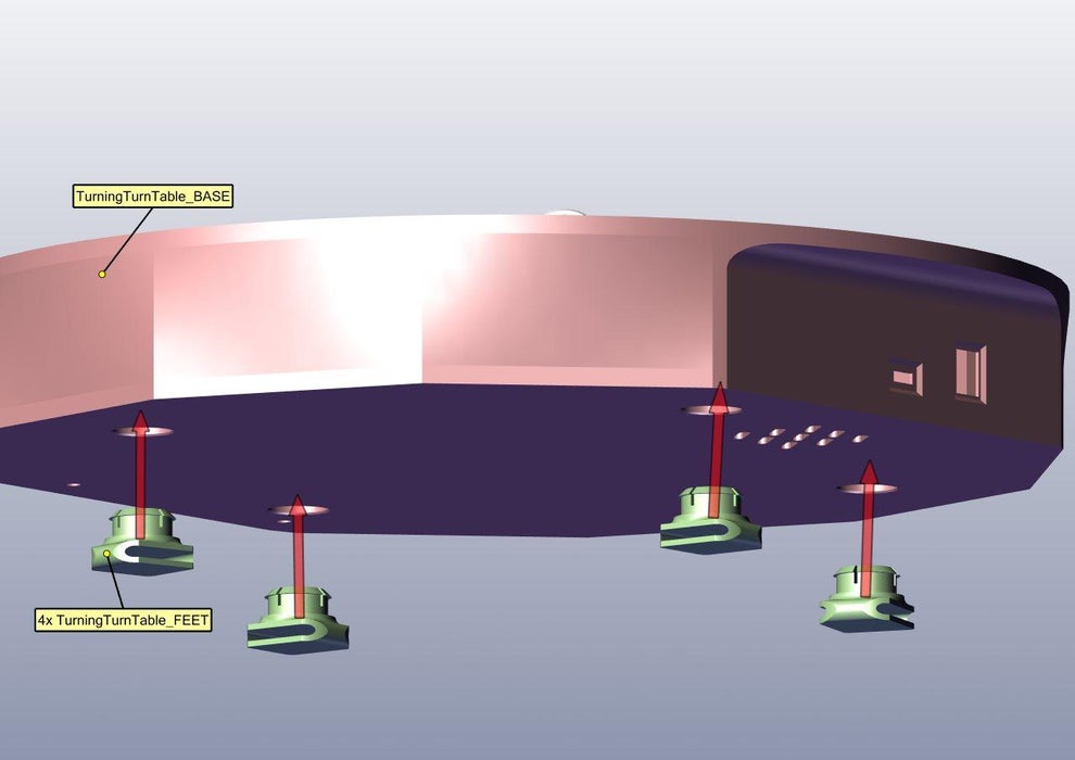
In the final mechanical assembly step of the turntable, insert the 4 legs into the base of the turntable from below.
Step 11: Assembly the Turntable Base – Finalization
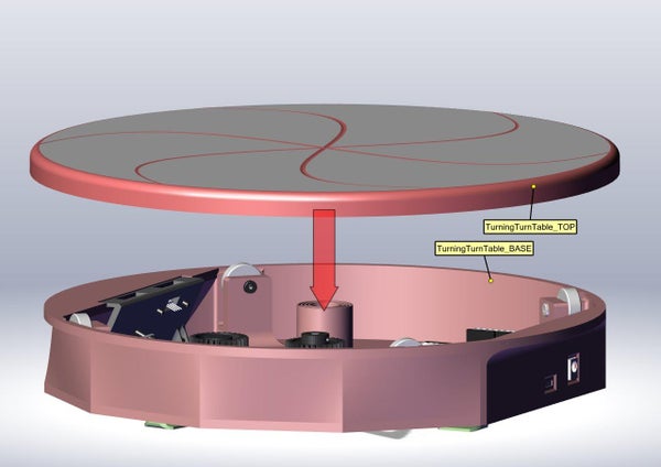
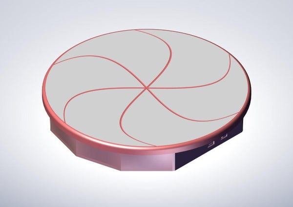
Now connect the top part and the base part together. Ensure that you can easily rotate the turntable by hand and that there are no wires or additional parts obstructing the movement inside.
Step 12: Setup Software
Download the latest repository from Github and upload the code to the ESP32-Arduino board using Visual Studio Code and PlatformIO. Before uploading, ensure the software configuration matches your setup:
- Select the correct board (ESP32 Arduino board or ESP32 DEV-Board).
- Verify the stepper motor type (28BYJ-48 or 17HS08).
- Confirm the stepper driver settings (HalfStepMode, FullStepMode, DriverMode).
Once these settings are verified and correct, rebuild the software and upload it to the board. Refer to the instructions in the Readme.md file of the repository for further guidance.
Step 13: Test the Correct Electronic Mount
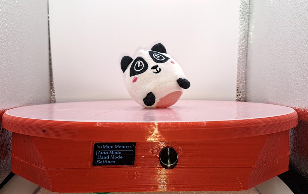
In this step, verify the functionality of the device by checking the following:
- Upon software upload, the OLED display should initialize and display the main menu. If not, review the pin definitions and ensure the correct LCD type is set in the software. Also, double-check the electrical wiring.
- Rotate the encoder to observe the selection bar on the display moving accordingly. Press the encoder to navigate through the corresponding submenus. If this does not occur, recheck the pin definitions in the software and verify the electrical connections.
- Enter Hand Mode on the display to manually operate the stepper motor. Use the encoder to select a 1/4 turn increment. The stepper motor should begin turning immediately. If not, confirm the correct definitions for the stepper motor and driver in use. If correctly defined, revisit the pin definitions and ensure accurate electrical connections.
Once these tests are successfully completed, the setup is almost complete!
Step 14: Check If the Smartphone You Use Is Supported
In this step, verify if your smartphone camera is supported. If not, please open an issue on GitHub or leave a comment here.
Navigate to the Settings Menu >> Auto Mode. Here, access a submenu to test the correct Bluetooth setup of the device. Upon selecting this option, a command is sent to the connected smartphone, and a screenshot should immediately appear on your phone’s screen. Ensure your smartphone is connected to the ESP32 device and the camera app is open.
Step 15: Enjoy
Congratulations! You’re all set!
To begin your fully automatic 360° photography, place the turntable in a well-illuminated area, position your favorite product on the platform, and set up your smartphone. Activate the automatic mode directly from the LCD display, and watch as it completes a full rotation and captures photographs seamlessly!
