

The DIY MidHUH? Controller is a custom-built, versatile MIDI controller designed for musicians and producers. It features programmable buttons, knobs, and sliders, allowing you to control various aspects of your digital audio workstation (DAW) with ease. This project is perfect for those looking to enhance their music production setup with a personalized, hands-on device. Follow the step-by-step guide to assemble the hardware, upload the firmware, and configure your controller for optimal performance..
Supplies
- 1x 400 pin breadboard
- 1x Teensy 4.1
- 1x micro USB cable
- 1x HW-103 moisture sensor
- 2x HC-SR04 OR 2x RCWL-1601 (these can be used interchangeably.)
- 4x EC11 rotary encoder with a switch
- 1x 7x10cm prototyping board
- 1x 3x7cm prototyping board
- About 2 meters of 26AWG wire (this is probably too much)
- A 3D printer
- Like 20 Dupont cables?
- A DAW (duh)
You can use any microcontroller with USB-host capabilities, but I’ve chosen the Teensy since it is faster, has way more Analog pins than a regular Arduino, is smaller than most Arduino’s and has interrupt capability on every pin. This is important to me since I had bigger plans and might expand this project later on, so having extra options is nice.
OPTIONAL:
- 2x 10k logarithmic potmeters
While they are soldered onto the PCB, I’ve opted not to use these. I found them to be a bit boring to use and not in the spirit of this project. You can map them to control the volume or other stuff, so if you really want to I’ve included the option to use them in the script later.
Step 1: Make It Your Own


I want to state that everything described in this Instructable should be taken as a rough guideline for your own controller. I urge you to get your hands on some weird stuff other than the stuff I’ve listed, because I personally think weirder sensors have the most potential to make cool music. Most sensors have an Arduino library available, so don’t be scared try some things!
I’ve personally experimented with a accelerometer-gyroscope combo sensor, and a pressure-temperature combo sensor, but I found them to be a bit cumbersome to use.
Step 2: Circuit Diagram

I started off making a circuit diagram to get a rough idea on how to connect everything together. If you’ve opted to use anything other than a Teensy 4.1 you’ll need to change some stuff around.
This diagram has been through a few iterations before I settled on this one. In the end it just came down to what kind of weird components I could find and reasonably connect to the Teensy. Be aware that the Teensy out of the box only supplies 3.3V instead of the Arduino’s 3.3V AND 5V. There is some trickery you can do to make the Teensy supply 5V through it’s USB port or dedicated 5V input, but be aware that using 5V on any other port can fry you Teensy.
You can refer to this step later when you start connecting stuff.
Step 3: Soldering


Since I’m a little scared of breaking stuff, I’ve opted to use a breadboard instead of soldering directly to the Teensy.
Make sure to tin the end of the wires if you are using stranded wires like me, since it’ll make inserting them into the breadboard way easier.
First of are the 4 rotary encoders. The brown and green wires are for sending the rotary’s position to the Teensy and the white one is ground. The blue and red cables on the other side are for using the build-in button. For this one it doesn’t matter which one is ground.
Then there are the 2 sonar sensors. Make sure you line them up like I did, or they won’t fit in the case. The black wires are for the signal, the white for power and the brown one for ground. Make sure you connect the wires to the sonar sensors at the bottom of the PCB with a little bit of solder.
Last up is the ground humidity sensor. You just need to solder 2 wires between the two parts.
And that’s it! As I’ve said before, you can solder more stuff if you pay close attention to the circuit diagram, but do it at your own risk.
Step 4: First Test

You’ll most likely need to install Teensyduino to get your Teensy to show up in the Arduino IDE and set it’s mode to MIDI.
https://www.pjrc.com/teensy/teensyduino.html
First off, make sure you install the USBMIDI library from Arduino’s website:
https://www.arduino.cc/reference/en/libraries/usbmidi
With everything soldered it’s probably a wise idea to make sure everything is wired correctly. Plug everything in according to the diagram from step 4 or the messy picture in this step. Note that the ground humidity sensor isn’t on this picture, so pay close attention to my instructions and the circuit diagram.
Here’s a checklist if you can’t figure it out.
- Grab a couple of short cables, and connect the 3.3v and ground on either sides to the breadboard.
- From pin 2 to 9: Connect the rotary encoder wires alternating between green and brown. Put the white ground in in negative
- Pins 21 to 19: Connect the rotary encoders blue and red wires, with one side going in a port, and the other side going in negative.
- For the FSR’s: Connect A5 to A7, and B6 to B8. Connect 2 10K resistors from A5 and B6 to negative. Put one side of the FSR in positive, and the other side in lane 5 or 6.
- The sonar’s: Put the two black wires on either side in port 39 and 38, and 29 and 30. White goes to positive, black to negative.
- Stick the ground humidity sensor in row A.
- The potmeters, again, are optional. You can route the cables underneath the PCB to an available analog port, but make sure you specify which ports you used in the script.
DO NOT TOUCH THE 5V output! The Teensy can’t handle anything over 3.3v, so be careful.
Attached at the bottom of this step is a script. Load it onto the Teensy and wait for it to compile. If everything is right you should see some stuff in the serial monitor. I’ve included a couple of lines code which check if everything is connected right. If the serial monitor doesn’t throw any errors, turn and push on the four rotary encoders to see if they print stuff in the serial monitor. If the serial monitor throws any errors or doesn’t detect the rotary encoders, make sure everything is soldered and connected correctly.
Now you are ready for the next step!
Attachments
Step 5: Assembly


I hope you warmed up your 3D-printer, because we’ll be using it right now! I had, uhh, trouble with my printer which I after a very long time solved by reinstalling my firmware. It did produce some interesting results though.
At the bottom of this step you can find 2 STL files: The top and bottom of the enclosure. This is the third version of the box. I got the design pretty right the first time around, so I only tweaked some minor things.
Printing these took me around 3 hours (disregarding the whole day it took to fix my broken printer) on an Ender 5 Pro. Once that’s done we can start assembling the controller.
On the bottom half there are 4 posts. Put the green PCB onto them.
Now take the breadboard and remove the film at the bottom. Line the Teensy’s micro usb port up with the hole in the side, and stick the breadboard onto the PCB.
Next are the rotary encoder and the FSR’s. Remove the film at the bottom of the FSR’s and stick them onto the top part. Route their cables through their dedicated holes. Stick the PCB with the rotary encoder through it’s dedicated slot and glue/tape it to the back of the top part. I’ve chosen for duct tape because I don’t want a permanent solution (yet).
Make sure to test everything again before closing it up!
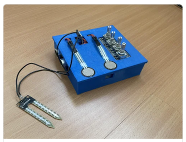
Gently close the controller while making sure all cables stay inside. Now stick the humidity sensor control board through the last slot at the top into the breadboard.
Attachments
Step 6: Connecting and Mapping
This is the tricky part because it varies from DAW to DAW. I can give you some general advice, but I’d rather provide some links with steps to connect MIDI-devices in some popular DAW’s. I had some trouble with Ableton not detecting my MIDI inputs, but this is fixed in the latest version of the script. Make sure you’ve set the Teensy to MIDI-mode.
FL Studio: https://www.image-line.com/fl-studio-learning/fl-studio-online-manual/html/app_wiz5.html
Ableton: https://help.ableton.com/hc/en-us/articles/360011853159-Using-MIDI-controllers-with-Live
Logic Pro: https://support.apple.com/en-gb/guide/logicpro/lgcp13f602e3/mac
Reaper: https://reaperaccessibility.com/wiki/Enabling_Midi_Devices
Cubase: https://www.steinberg.net/tutorials/connect-audio-hardware-to-cubase/
In terms of mapping the controls to parameter I also don’t have much to add. As a test you can map every control to separate volume sliders, but apart from that: Good luck! Experimenting with this thing is 90% of the fun for me, so go figure it out!
Step 7: Enjoy!

And that’s it! I’ve been using this controller for my latest song which I hope to release sometime soon. To be very honest, the MidHUH? controller has been a bit cumbersome to use, but it has led to some interesting stuff. It was quite a struggle to get the Teensy to spit out usable data, but once I got that working it was a pretty smooth ride with some experimentation along the way.
I’m satisfied with the project so far, but I’ll probably do a version 2 with a nicer, more ergonomic exterior and more weird sensors I ever get around to it.
Thanks for following along!


