
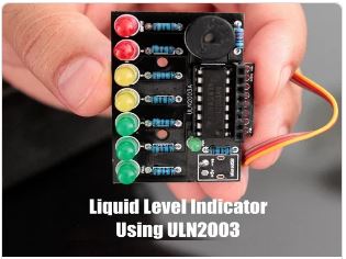
In this tutorial, I am going to use the ULN2003 IC to create a simple, inexpensive water level indicator.
Supplies

For this tutorial we need:
- 1 x ULN2003 IC
- 8 x Different Color LEDs
- 8 x 220Ohm Resistors
- 1 x 100Ohm Resistor
- 1 x Buzzer
- A Long Ribbon Cable, and
- A Breadboard or a Custom Built PCB
Step 1: About the ULN2003 IC


The notch on the top indicates the starting and stopping points of the numberings of the chip. Starting from left to right going counterclockwise this is the Pin number 1 of the IC.
* On the left hand side Pin 1 to 7 are the Base Inputs.
* On the right hand side Pin 10 to 16 are the Collector Outputs.
* Pin 9 is the Common Cathode node for flyback diodes (required for inductive loads).
* And, Pin 8 is the Common Emitter shared by all channels of the IC. This pin is typically tied to ground.
The UNL2003 IC contains 7 High Voltage, High Current NPN Darlington Transistor Arrays each rated at 50V, 500mA in a 16-pin DIP package. You can connect the IC directly to a digital logic (like Arduino or Raspberry Pi, TTL or 5V CMOS device) without an external dropping resistor. The ULN2003 is known for its high current and high voltage capacity.
The Darlington pairs can be “paralleled” for higher current Output.
To know more about this IC, please check out my “Tutorial No. 51: All About ULN2003 IC”, the link is in the description below.
Step 2: Circuit Diagram

The circuit is very simple.
I have connected 7 LEDs to the 7 OUT Pins of the IC via 1K Resistors.
On my left, are the 7 digital inputs which are connected to a ribbon cable. The other end of the ribbon is submerged in the water tank with exposed terminals at various heights to detect the water levels. Along with the 7 wires, there is an eighth wire that stays at the bottom of the tank and is connected to the +ve terminal.
As the tank starts filling up, the water level rises and a conductive path is created between the positive terminal and the base of Darlington Transistor inside the IC. Hence a logic HIGH is sent to the Input Pin of the IC which leads to the corresponding OUT Pin to go LOW lighting up the LEDs one by one starting from the bottom Red to the top Green. The bottom Red LED indicates lack of water and the top Green LED indicates that the tank is 100% full.
You can also add a buzzer to the circuit to get an audio indication when the tank is full.
If you want to be super funky, you can also add a relay module which can turn on and off the water pump.
Step 3: Breadboard Demo

Before assembling the components on a PCB, lets do a quick test on a breadboard to make sure our logic works as expected.
For this demo, I am going to fill up a coffee mug with normal tap water.
As you can see, the LED indicators go up from bottom Red to the top Green as I keep filling the mug. The buzzer starts buzzing when the mug is 100% full. Hence, our setup is working as expected.
Step 4: The Board

So, this is how my board looks like in 2D and 3D.
If you want to learn how to design a PCB, please check out my “Tutorial No. 45: Transformers PCB BADGE”, the link is in the description below.
Step 5: Component Assembly


Now, lets solder the components to the board.
Lets first solder all the resistances to the board.
Then, lets solder all the LEDs to the board. I am using a 3mm Green LED as the power indicator.
Next, I am soldering the IC base to the board. Since I care a lot about my ICs and micro-controllers, I never solder them directly to the board. In case of an ICs, I always try to use an IC bases or if a base is not available I use female pin headers.
After soldering the IC base, I am soldering the Buzzer to the board.
Now to conclude the setup, I am soldering the Ribbon Cable to the board. For my setup, I am only using half a meter long cable. But in a real-world scenario, you will definitely need a cable longer than this.
Step 6: Final Demo

So, this is how the final setup looks like.
As the water level rises, a conductive path is created between the positive terminal and the base of Darlington Transistors inside the IC. This triggers a logic HIGH at the Input Pins of the IC and the corresponding OUT Pins goes LOW lighting up the LEDs one by one starting from the bottom Red to the top Green. When the mug is 100% full the top green LED lights up and we also hear a noises of the buzzer.
Step 7: Usability

To be very frank, I see more disadvantages than advantages of using this IC in building a liquid level indicator.
- You may have a different opinion, but my opinion is based on the below facts:The choice of the probes that will remain submerged in the liquid has to be done very carefully as they:
- Rust, foul and deteriorate due to “corrosion” and “electrolysis” causing the LEDs to slowly fade and finally turn off.
- Hence the probes need to be cleaned and replaced every 2 – 3 years.
- This circuit will work well with tap water, however do not use this with salt water or with any flammable liquid. If in your house you get hard-water, there will be salt deposits on the probes and you will have to clean the salt deposits on a regular basis.
- This circuit will not work if you have a metal tank.
Replacing the contact points with something “non-corrosive” may help but I will not put my bet on that.
Another option is to have “large electrodes” which will have a low impedance even when covered with impurities.
To conclude I would like to say that the ULN2003 is not the best device to use for this application. You might be better using a “CMOS buffer” or inverter which needs less water conductivity to operate and also gives a more sudden output change as the input voltage rises and falls, along with “non-corrosive large electrodes”.
Step 8: Thanks
Thanks again for checking my post. I hope it helps you.
If you want to support me subscribe to my YouTube Channel: https://www.youtube.com/user/tarantula3
References
- Gerber: View
- DataSheet: Download
- All About ULN2003 IC: View
- Transformers PCB BADGE: View
- DIY Relay Module: View
Support My Work
- BTC: 1Hrr83W2zu2hmDcmYqZMhgPQ71oLj5b7v5
- LTC: LPh69qxUqaHKYuFPJVJsNQjpBHWK7hZ9TZ
- DOGE: DEU2Wz3TK95119HMNZv2kpU7PkWbGNs9K3
- ETH: 0xD64fb51C74E0206cB6702aB922C765c68B97dCD4
- BAT: 0x9D9E77cA360b53cD89cc01dC37A5314C0113FFc3
- LBC: bZ8ANEJFsd2MNFfpoxBhtFNPboh7PmD7M2
- COS: bnb136ns6lfw4zs5hg4n85vdthaad7hq5m4gtkgf23 Memo: 572187879
- BNB: 0xD64fb51C74E0206cB6702aB922C765c68B97dCD4
- MATIC: 0xD64fb51C74E0206cB6702aB922C765c68B97dCD4