
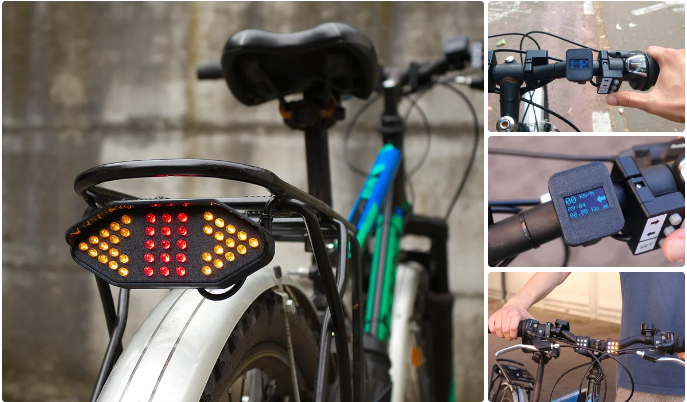


In this guide, we will show you how we built a versatile bicycle lighting system using an Arduino. This system not only includes powerful headlights but also features turn signals for indicating direction and an odometer that displays speed, time, and total distance traveled. Living in a small town, I rely on my bicycle for most of my transportation, and having highly visible headlights makes biking much safer, especially at night.
My design incorporates headlights that emit either white or red light, along with yellow indicators to signal turns. To activate the turn signals, we have buttons mounted on the handlebars. These buttons also allow us to navigate through the information on the display and to turn the lights on or off. The display, located next to the buttons, shows real-time data such as current speed, time, total kilometers traveled, and other useful ride information.
The headlights are designed to be extremely bright, ensuring visibility both during the day and at night. The entire system is controlled by an Arduino and powered by a battery that can be conveniently charged via a USB-C port. Additionally, I have devised a method to conceal all the electronics on the bike, reducing the risk of theft.
By following this guide, you will be able to create a comprehensive bicycle lighting and information system that enhances safety and provides valuable ride data, all while keeping the electronics discreetly hidden.
Supplies


To make this project, we used:
- Arduino Nano board (link here)
- 0.96″ 128×64 monochrome OLED display with i2c communication (link here)
- 3 12×12 mm tactile switches (link here)
- 2 US5881 Hall effect sensors (one is optional; link here)
- DS3231 Real Time Clock module (link here)
- 4 IRFZ44N mosfets
- 18650 lithium-ion battery cell
- TP4056 USB-C charger board (link here)
- 5V 500 mA (or more) boost step-up module
- Rocker switch
- ~ 5 meters-long 26 AWG 4-core cable (link here)
- Perfboard
- 4 220 Ohm resistors
- 6 10K Ohm resistors
- 2 2.2K Ohm resistors
- 1 100K Ohm resistor
- 1 20K Ohm resistor
- 15 clear red 5 mm LEDs
- 40 clear yellow 5mm LEDs
- 6 clear white 5 mm LEDs
- 27 47 Ohm resistors
- 6 130 Ohm resistors
- 1 330 Ohm resistor
- 5 4-pin JST XH 2.54 mm connectors (male and female; link here)
- 2 3-pin JST XH 2.54 connectors (male and female; link here)
- 1 clear red 3 mm LED and 1 clear blue 3 mm LED
- 2 M3 brass threaded inserts (link here)
- M3 12 mm-long bolts (link here)
- M3 20 mm-long bolts (link here)
- M3 self-locking nuts (link here)
- Heat-shrink tubes of various sizes
- Bike water bottle
Tools we used for this project:
- 3D printer with black PLA filament
- Soldering iron
- Hot glue
- Screwdrivers, pliers and other basic tools
Step 1: Overview


This project is divided into several parts. First we have the two headlights at the front and back, which in addition to the traditional red and white light also have the two turn signals to indicate direction. On the handlebar things get more interesting, because we have a display, which shows the speed we are going, the time, total kilometers, and other interesting information about our ride. Next to the display we have three buttons, with which we can activate the arrows, change the pages on the display and turn the headlights on or off. As a last thing we have a magnetic sensor that detects the revolutions of the bike wheels in order to calculate the speed and show it on the display. All these components are connected to a circuit that includes an Arduino, a Real Time Clock module, and four mosfets, which are used to control the LEDs in the headlights. The whole system is powered by a lithium-ion battery, which is charged via a USB-C port. And if you were wondering… yes, all the electronics are hidden in a bike-mounted water bottle, but more about that later.
Designing this whole thing together was too complicated, so somewhat randomly we started with the part that seemed the simplest: the rear light.
Step 2: Rear Light


To make the rear light, I used 15 clear red 5 mm LEDs for the rear light and 28 clear yellow 5 mm LEDs for the turn signals (14 for each indicator). It was important for the rear light to be clearly visible even in daylight, so maybe I used too many LEDs.
First, we designed and 3D printed a housing for the headlight and a plate with holes in which to mount the LEDs (the STL files for 3D printing can be found below). On the back, the plate has two spacers with holes, in which I put two M3 brass threaded inserts, using a soldering iron to heat them. These threaded inserts will be used later to secure the LEDs to the enclosure.
Now we need to mount and connect the LEDs. The LEDs can be inserted in the holes of the mounting plate, taking care of using red LEDs in the centre and yellow LEDs at the sides. The LEDs will be connected in series of two, and each series will have a 47 Ohm resistor. All of the series of two will then be connected in parallel, separated into three groups for the center red and the left and right turn signals.The three groups of LEDs will share the +5V pin, while the three grounds will be used to control separately the red light and the two yellow indicators. To make the connections I simply bent and soldered together the pins of the LEDs and resistors. Using this technique the circuit may look very complex, but in fact it is just a simple connection repeated many times. Anyway, below you can find the schematics that you can follow while making the connections (the back light is on page 4). It is importante to note that, by connecting the LEDs in series of two, the center red light, that has 15 LEDs, will have one extra LED. To solve this issue, I simply connected a 330 Ohm resistor to its positive pin and connected it in parallel with the other red LEDs.
Then we inserted into the enclosure a four-pin cable, which will be used to connect the rear light to the control circuit. I soldered one wire to the common positive, and the other three to the negatives of the three groups of LEDs. Before closing the light I did a test with the bench power supply, in order to check if all the LEDs were working correctly. Then I covered the connections on the back of the LEDs with hot glue, in order to prevent short circuits between the wires.
In the light housing I inserted two M5 hex bolts into the holes on the back of the enclosure, that have an hexagonal space in which the head of the bolts can be fit. These bolts will be used to attach the rear light to the bicycle. As a last thing, I closed the light with two M3 bolts screwed into two threaded inserts.
To the other end of the cable, I connected a four-pin JST connector, that will be used to connect the light to the main circuit board.
Step 3: Display


Once the rear light was completed we took care of the display that will be on the handlebars of the bike, which will allow us to see interesting information such as speed and total route. The display I chose is a small 0.96″ 128×64-pixel monochrome OLED screen with i2c communication. The i2c communication allows us to connect the display directly to the Arduino using only 4 wires, two for 5V power (+5V and GND) and two for data (SDA) and clock (SCL). In order to make the display more compact, I removed the jumper headers that were soldered to the PCB. To connect the display to the Arduino I will use the same four-pin cable I had used for the rear light. This time the connections are very simple: I needed to solder the four wires of the cable to the four pads for +5V, GND, SDA, SCL that are on the display PCB.
To mount the display on the handlebar, I designed and 3D printed a part that can be secured on the handlebar and a small enclosure in which to mount the display. I glued the display into the enclosure, being careful to align it to the opening. Then I ran the cable out of the hole in the base. The enclosure with the display can be secured to the base thanks a snap fit that was designed in the 3D-printed parts. As a last thing, I inserted two M3 self-locking nuts into the openings in the mount, which will be used to secure the display on the handlebar with screws.
As I did for the rear light, to the other end of the cable, I connected a four-pin JST connector, that will be used to connect the display to the main circuit board.
Step 4: Buttons


Once the display was finished, I thought about the buttons that will be used to activate the turn indicators and control the display. We will have three buttons: two for the left and right turn signals and another one that can be used to navigate through the pages on the display, that in my project I labelled as “SET”. After looking at different types of buttons I chose to use some 12×12 mm tactile switches, because they are very compact and inexpensive.
To secure the buttons to the bike, I 3D printed a mount very similar to the one of the display, that is composed of a part that can be secured to the bike and an enclosure. Before putting the buttons in the 3D printed mount, I straightened the pins and cut them flush on one of the two sides (the pins of one side are mirrored on the other side). Then I put the buttons in the 3D printed mount, holding them temporarily with some double sided tape.
Also for this part the connections are very simple. Each button will be connected between the common GND and one of the pins of the Arduino. Like for the other parts, to connect the buttons to the Arduino i used a four-pin cable. I soldered one of the four wires to the common ground of the switches, and the other three to the free pin of each button, as you can see from the pictures. After checking the connections, I secured the buttons to the mount with hot glue. Then I 3D printed, using grey PLA, a small cap that I inserted on each of the three buttons. As a last thing I put the enclosure onto the mount with a snap fit that is designed into the 3D printed parts. As I did for the display, I inserted two M3 self-locking nuts into the openings in the mount, which will be used to secure the display on the handlebar with screws.
As I did for the other parts, to the other end of the cable I connected a four-pin JST connector, that will be used to connect the light to the main circuit board.
Step 5: Front Lights


Now it was time to make the front light, that is built in a very similar way to the back light. Actually, the front light is divided into two separate lights. These will be mounted on the bicycle handlebars with the same system used for the display and buttons. Each of the two lights will have three white LEDs for the main light, and six yellow ones, for the left or right indicator.
Again, I designed some pieces to be 3D printed. Like for the rear light, for each of the two front lights we have an enclosure, that includes a mount that can be secured to the bike handlebar (the same concept used for the display and buttons), and a panel with holes in which to insert the LEDs. First, I inserted the LEDs in the holes in the panel, creating one column of white LEDs and two of yellow LEDs. Then it was time to make the connections. The yellow LEDs are connected in series of two, with a 47 Ohm resistor for each serie. The three series of yellow LEDs are then connected in parallel, as we have done in the rear light. On the other hand, the white LEDs require a higher voltage, so I put a 130 Ohm resistor for each one and then connected all three of them in parallel. To make the connections I simply bent and soldered together the pins of the LEDs and resistors. Since we need to make two headlights, I made two identical circuits, that have the LED colors mirrored (on the final assembly, the white LEDs will stay on the inside while the yellow LEDs will stay on the outside).
Also for the front lights, I used a four-pin cable for the connections. It is important to note that, while the 3D printed enclosures of the two lights look just mirrored, one of them has two holes for the cables, while the other one only has one. I inserted the cable that will connect the front lights to the main controller into the enclosure that has two holes. Using a short piece of cable, I connected the first enclosure to the second one. The connections are quite simple. As for the rear light, all the LEDs share a common positive connection, while the negatives are used to control the individual groups of LEDs. So, I soldered the +5V wire that comes from the main circuit to the positive of the LEDs of the first light and to one of the wires that go to the second light, where I also soldered it to the common positive of the LEDs. The same goes for the GND of the white LEDs, which is common for both front lights. The GND for the right turn signal is directly soldered to the negative of the yellow LEDs of the first light. The GND for the left indicator is firstly soldered to one of the wires of the cable that goes to the second light, and then to the negative of its yellow LEDs.
After testing the LEDs I protected the connections with hot glue. As a last thing, I snap-fitted both LED panels into their enclosures. As I did for the display and for the buttons, I inserted two M3 self-locking nuts into the openings in the mount of each light, which will be later used to secure the display on the handlebar with screws.
Also here, to the other end of the cable I connected a four-pin JST connector, that will be used to connect the light to the main circuit board.
Step 6: Speed Sensor


As I said before, on the display we will also see the speed at which we are riding. To measure speed, I discarded more complicated things like GPS, and chose the simplest (and maybe most accurate) system: a magnetic sensor mounted near the rear wheel of the bike, which detects a magnet attached to the wheel itself. This way, the sensor is triggered for each revolution of the wheel. By reading how many times the sensor is triggered in a defined time interval (in my case, 5 seconds) the Arduino is able to calculate the revolutions per minute of the wheel and then convert them into the speed in kilometers per hour, by knowing the circumference of the wheel.
The sensor I chose is a US5881 Hall effect sensor. The sensor has three pins, +5V and ground for power and an output pin. In order to connect the sensor to the Arduino I used the same four-pin cable I used for the other components. I soldered three of the four wires to the three pins of the sensor, of course leaving one wire free. Then I protected the sensor and the individual connections with heat shrink tubing. To the other end of the cable I connected a fthree-pin JST connector, that will be used to connect the light to the main circuit board.
To mount the sensor to the bike I made a small 3D printed stand. The sensor wire can be inserted into a hole in the mount, and then the sensor itself can be secured using two zip ties. The mount with the sensor will then be secured near one of the wheels of the bike using zip ties.
In order to trigger the sensor I used a magnet that I already had secured to the wheel of my bike, that was recovered from some old magnet-powered bike lights. However, you can use any magnet that is strong enough to trigger the sensor reliably at a distance of around 1 centimeter, and secure it to the wheel.
Step 7: Control Board – Arduino and RTC


Now that we have all the components of the system, we need to make the board with the Arduino to which they will be connected. To make it, I started with a piece of perfboard of around 55×90 mm, onto which I soldered an Arduino Nano using some jumper headers. In addition to the Arduino, I put a DS3231 Real Time Clock module on the board, which will be used to keep the time we see on the display even when the Arduino is turned off. To do this, normally the RTC is powered by a 3V coin cell, which with such low power consumption can last for several years. In this project we will already have a rechargeable lithium-ion battery that will power the whole system, and having a second battery that periodically needs to be changed did not make sense. So I decided to modify the RTC module in order to power it directly from the main battery. The first thing I did was to remove the small resistor above the SCL pin on the PCB: this resistor is used to slowly charge the coin cell that we would normally put on the RTC, which is something that we don’t want with the external battery. Then I desoldered the coin cell holder, to save some space. As a last thing I soldered a piece of wire to the pad to which the positive of the coin cell was connected (in my case it was the one near the status LED, but it is better to check with a multimeter). This wire will simply be connected to the positive of the main 18650 li-ion battery.
Step 8: Control Board – Mosfets, I2C and Voltage Divider


Once the RTC was in place I soldered onto the board two four-pin JST connectors to for the display and the buttons, and two JST connectors for the wheel revolutions sensor and another magnetic Hall effect sensor to detect when we brake, which in the end I did not install. If you are interested, this last magnetic sensor would have been used to increase the brightness of the rear light when we press the brake. For the two magnetic sensors, I put in 10K Ohm pullup resistors between the signal pin and the +5V power. The best place to put these resistors is near the connectors.
To control the headlight LEDs from the Arduino pins I used IRFZ44N mosfets, two for the left and right turn signals and two for the front and back lights. For each mosfet, I put a 10K Ohm resistor between the gate and GND. The gate of each mosfet is connected to one Arduino pin, with a 220 Ohm resistor in between. To connect the rear and front light, I soldered two four-pin JST connectors to the board, to which I brought the +5V power and the grounds for the different lights coming from the drains of the four mosfets.
The display and RTC module will be connected to the Arduino via i2c using pins A4 and A5. On both i2c lines I put 2.2K Ohm pullup resistors, connected between each one of the i2c lines and +5V power.
To measure the battery voltage and show it on the display, I used an analog pin on the Arduino, to which I connected a voltage divider composed of two resistors (a 100K Ohm one a 20K Ohm one) in order to bring the battery voltage to a value below the 1.1V internal reference of the Arduino.
Once all the components were soldered to the board I made the connections under the board following the wiring diagram that you can find below. To make the connections I used a combination of solid copper wire and wires with silicone sheating. This work obviously took some time, but finally I was able to finish the board. If you prefer, following the schematic you can design you own PCB to be manufactured.
Step 9: Arduino Code


Before installing the system, we need to upload the code to the Arduino. Writing the code was perhaps the longest and most complex part of this project. Certainly the code is not well written, however it works and that is what is important. The code takes care of measuring the speed, reading the time from the RTC, controlling the lights and turn signals and showing the interface on the display… there’s a lot going on. The good news is you don’t need to modify the code if you don’t want to: all the settings can be done directly from the interface on the display. These settings are of course saved into the EEPROM, so that they remain even when the system is powered off.
Before uploading the code, I suggest to unplug the Arduino from the board. The code can be compiled and uploaded from the Arduino IDE, after installing the Adafruit_SSD1306 library and the RTClib library.
Below you can find the code to download, which is what I suggest. If you prefer, you can copy it directly from here and paste it into the Arduino IDE.
#include <SPI.h>
#include <Wire.h>
#include <Adafruit_GFX.h>
#include <Adafruit_SSD1306.h>
//#include <Adafruit_SH1106.h>
#include "RTClib.h"
#include <EEPROM.h>


#define SCREEN_WIDTH 128 // OLED display width, in pixels
#define SCREEN_HEIGHT 64 // OLED display height, in pixels


#define OLED_RESET     -1 // Reset pin # (or -1 if sharing Arduino reset pin)
//#define OLED_RESET     12 // Reset pin # (or -1 if sharing Arduino reset pin)
#define SCREEN_ADDRESS 0x3C ///< See datasheet for Address; 0x3D for 128x64, 0x3C for 128x32
//#define i2c_Address 0x3c
Adafruit_SSD1306 display(SCREEN_WIDTH, SCREEN_HEIGHT, &Wire, OLED_RESET);
//Adafruit_SH1106 display = Adafruit_SH1106(OLED_RESET);


RTC_DS3231 rtc;


float wheelCircumference = 2.00; //meters (can be set from the settings page of the device)
const float speedUpdateInterval = 5000; //calculate speed every N milliseconds


const long turnSignalBlink = 500; //speed at which the turn signals blink in milliseconds
const int turnSignalMaxCycles = 12; //number of turn signal blinks before they turn off automatically


const int wheelSensor = 2; //pin to which the wheel hall effect sensor is connected


const int brakeSensor = 7; //pin to which the brake hall effect sensor is connected
const bool invertBrakeSensor = false; //true: brake detected when the magnet is far from the sensor


const int LEFTbutton = 3; //pins to which the three buttons are connected
const int RIGHTbutton = 4;
const int SETbutton = 5;


const int LEFTled = 9; //pins to which the lights are connected
const int RIGHTled = 10;
const int REDled = 11;
const int WHITEled = 6;


float totalKm = 0; //variable that stores total distance
float speed = 0; //variable that stores current speed
float maxSpeed = 0; //variable that stores maximum speed
float avgSpeed = 0; //variable that stores average speed
long activeTime = 0; //variable that stores active time


float speedMillis = 0; //milliseconds from the last time speed was calculated


bool frontLights = false; //state of front lights
bool backLights = true; //state of back lights
bool brakeLights = false; //state of brake lights
bool left = false; //state of left turn signal
bool right = false; //state of right turn signal
bool turnSignalState = true;
bool lastLeftState = true;
bool lastRightState = true;


bool leftReleased = true;
bool rightReleased = true;
bool setReleased = true;


int lightsCycle = 0;
int turnSignalCycle = 0;
long previousMillis = 0;
long releaseMillis = 0;
long lightsMillis = 0;


int displayPage = 0; //0: home screen - 1: info screen - 2: control screen
int menuSelection = 0;
bool pageUpdated = false;


int batteryState = 0;
const int batteryReadingDeadband = 10;


int pulses = 0;


void setup() {
  pinMode(wheelSensor, INPUT);
  pinMode(brakeSensor, INPUT);
  pinMode(LEFTbutton, INPUT_PULLUP);
  pinMode(RIGHTbutton, INPUT_PULLUP);
  pinMode(SETbutton, INPUT_PULLUP);
  pinMode(LEFTled,  OUTPUT);
  pinMode(RIGHTled, OUTPUT);
  pinMode(REDled, OUTPUT);
  pinMode(WHITEled, OUTPUT);


  analogReference(INTERNAL);


  //Serial.begin(9600);


  display.begin(SSD1306_SWITCHCAPVCC, SCREEN_ADDRESS);
  //display.begin(SH1106_SWITCHCAPVCC, 0x3C);


  rtc.begin();


  //rtc.adjust(DateTime(F(__DATE__), F(__TIME__)));


  display.clearDisplay();
  display.setTextSize(2);
  display.setTextColor(WHITE);


  for(int i = -20; i <= 24; i++) {
    display.fillRect(0, 0, 128, 64, BLACK);
    display.setCursor(28, i);
    display.print("Hello!");
    display.display();
    delay(2);
  }
  delay(500);


  display.clearDisplay();
  delay(200);

  bool settings = false;
  bool settingsChanged = false;
  int settingsPage = 0;
  int selection = 0;


  DateTime now = rtc.now();
  int h = now.hour();
  int m = now.minute();


  EEPROM.get(0, wheelCircumference);


  //enter settings when the SET button is pressed during startup
  if(digitalRead(SETbutton) == 0 || isnan(wheelCircumference)) {
    setReleased = false;
    delay(100);
    display.clearDisplay();
    settings = true;
    //remain into the settings
    while(settings == true) {
      //detect if the SET button has been released after being pressed
      if(digitalRead(SETbutton) == 1 && setReleased == false) {
        setReleased = true;
        delay(100);
      }


      //main settings menu
      if(settingsPage == 0) {
        display.fillRect(0, 0, 128, 64, BLACK);


        //move between the settings using the LEFT and RIGHT buttons
        if(digitalRead(RIGHTbutton) == 0) {
          selection++;
          if(selection > 3) selection = 0;
          delay(200);
        }


        if(digitalRead(LEFTbutton) == 0) {
          selection--;
          if(selection < 0) selection = 3;
          delay(200);
        }


        display.setTextColor(WHITE);
        display.setTextSize(2);
        display.setCursor(15, 0);
        display.print("Settings");


        display.drawLine(0, 28, 127, 28, WHITE);
        display.drawLine(0, 52, 127, 52, WHITE);
        display.setCursor(0, 33);
        display.print("<");
        display.setCursor(116, 33);
        display.print(">");


        if(selection == 0) {
          display.setCursor(18, 33);
          display.print("Exit");


          //exit from the settings if "Exit" is selected
          if(digitalRead(SETbutton) == 0 && setReleased == true) {
            settings = false;
            delay(200);
          }
        }


        if(selection == 1) {
          display.setCursor(18, 33);
          display.print("Time");
        }


        if(selection == 2) {
          display.setCursor(18, 33);
          display.print("Wheel");
        }


        if(selection == 3) {
          display.setCursor(18, 33);
          display.print("Sensors");


        }


        //if SET is pressed, go into the menu that has been chosen
        if(digitalRead(SETbutton) == 0 && setReleased == true && selection != 0) {
          settingsPage = selection;
          selection = 0;
          setReleased = false;
          display.clearDisplay();
          delay(200);
        }
        //display.display();
      }


      display.display();

      //settings page for entering the current time
      if(settingsPage == 1) {
        display.fillRect(0, 0, 128, 64, BLACK);


        //move between the settings using the SET button
        if(digitalRead(SETbutton) == 0 && setReleased == true) {
          selection++;
          if(selection > 2) selection = 0;
          setReleased = false;


          delay(200);


          //Serial.println(selection);
        }

        if(selection == 0) {
          display.fillRect(0, 0, 128, 18, WHITE);
          display.setTextColor(BLACK);


          if(digitalRead(RIGHTbutton) == 0 || digitalRead(LEFTbutton) == 0) {
            settingsPage = 0;
            if(settingsChanged == true) {
              rtc.adjust(DateTime(2024, 1, 1, h, m, 0)); //set date-time manually: yr, mo, dy, hr, mn, sec
              settingsChanged = false;
              settingsConfirmation();
              delay(1200);
              display.clearDisplay();
            }
            delay(200);
          }
        }


        else {
          display.fillRect(0, 0, 128, 18, BLACK);
          display.setTextColor(WHITE);
        }

        display.setTextSize(2);
        display.setCursor(0, 2);
        display.print("<");
        display.setCursor(18, 2);
        display.print("Set time");


        display.setTextSize(3);


        if(selection == 1) {
          display.fillRect(14, 29, 41, 25, WHITE);
          display.setTextColor(BLACK);


          if(digitalRead(RIGHTbutton) == 0) {
            h++;
            if(h > 23) h = 0;
            settingsChanged = true;
            delay(200);
          }


          if(digitalRead(LEFTbutton) == 0) {
            h--;
            if(h < 0) h = 23;
            settingsChanged = true;
            delay(200);
          }
        }


        else {
          display.fillRect(14, 29, 41, 25, BLACK);
          display.setTextColor(WHITE);
        }


        display.setCursor(18, 31);
        if(h < 10) display.print(0);
        display.print(h);


        display.setTextColor(WHITE);
        display.print(":");


        if(selection == 2) {
          display.fillRect(68, 29, 41, 25, WHITE);
          display.setTextColor(BLACK);


          if(digitalRead(RIGHTbutton) == 0) {
            m++;
            if(m > 59) m = 0;
            settingsChanged = true;
            delay(200);
          }


          if(digitalRead(LEFTbutton) == 0) {
            m--;
            if(m < 0) m = 59;
            settingsChanged = true;
            delay(200);
          }
        }


        else {
          display.fillRect(68, 29, 41, 25, BLACK);
          display.setTextColor(WHITE);
        }


        if(m < 10) display.print(0);
        display.print(m);


        //display.display();
      }


      if(settingsPage == 2) {
        display.fillRect(0, 0, 128, 64, BLACK);


        if(isnan(wheelCircumference)) wheelCircumference = 2.0;


        if(digitalRead(SETbutton) == 0 && setReleased == true) {
          selection++;
          if(selection > 1) selection = 0;
          setReleased = false;


          delay(200);
        }

        if(selection == 0) {
          display.fillRect(0, 0, 128, 18, WHITE);
          display.setTextColor(BLACK);


          if(digitalRead(RIGHTbutton) == 0 || digitalRead(LEFTbutton) == 0) {
            settingsPage = 0;
            if(settingsChanged == true) {
              EEPROM.put(0, wheelCircumference);
              settingsChanged = false;
              settingsConfirmation();
              delay(1200);
              display.clearDisplay();
            }
            delay(200);
          }
        }


        else {
          display.fillRect(0, 0, 128, 18, BLACK);
          display.setTextColor(WHITE);
        }

        display.setTextSize(2);
        display.setCursor(0, 2);
        display.print("<");
        display.setCursor(18, 2);
        display.print("Set wheel");


        display.setTextSize(3);


        if(selection == 1) {
          display.fillRect(6, 27, 113, 29, WHITE);
          display.setTextColor(BLACK);


          if(digitalRead(RIGHTbutton) == 0) {
            wheelCircumference += 0.01;
            if(wheelCircumference > 5.00) wheelCircumference = 5.00;
            settingsChanged = true;
            delay(150);
          }


          if(digitalRead(LEFTbutton) == 0) {
            wheelCircumference -= 0.01;
            if(wheelCircumference < 0.10) wheelCircumference = 0.10;
            settingsChanged = true;
            delay(150);
          }
        }


        else {
          display.fillRect(6, 27, 113, 29, BLACK);
          display.setTextColor(WHITE);
        }


        display.setCursor(10, 31);
        display.print(wheelCircumference);
        display.setTextSize(2);
        display.setCursor(93, 38);
        display.print("mt");


       // display.display();
      }


      if(settingsPage == 3) {
        display.fillRect(0, 0, 128, 64, BLACK);

        if(digitalRead(RIGHTbutton) == 0 || digitalRead(LEFTbutton) == 0) {
          settingsPage = 0;
          delay(200);
        }


        display.fillRect(0, 0, 128, 18, WHITE);
        display.setTextColor(BLACK);
        display.setTextSize(2);
        display.setCursor(0, 2);
        display.print("<");
        display.setCursor(18, 2);
        display.print("Sensors");


        display.setTextColor(WHITE);
        display.setCursor(0, 26);
        display.print("Wheel: ");
        if(digitalRead(wheelSensor) == 0) {
          display.print("ON");
        }
        else {
          display.print("OFF");
        }
        display.setCursor(0, 48);
        display.print("Brake: ");
        if(digitalRead(brakeSensor) == 0) {
          display.print("ON");
        }
        else {
          display.print("OFF");
        }
      }
    }
  }


  EEPROM.get(0, wheelCircumference);


  //Serial.println(wheelCircumference);


  attachInterrupt(digitalPinToInterrupt(wheelSensor), interruptFunction, RISING);
}


void loop() {
  //update the display every 250ms
  if(millis() % 250 == 0) {
    update();
  }


  if(millis() - lightsMillis >= 180) {


    lightsMillis = millis();


    lightsCycle++; //0 to 1: red bright - 2 to 5: red dim
    if(lightsCycle > 5) lightsCycle = 0;
  }


  if(millis() - speedMillis >= speedUpdateInterval) {


    calculateSpeed();


    speedMillis = millis();
  }


  if(frontLights == true) {
    if(left == true || right == true) {
      analogWrite(WHITEled, 20);
    }
    else {
      analogWrite(WHITEled, 180);
    }
  }


  if(frontLights == false) {
    analogWrite(WHITEled, 0);
  }


  //blinking red headlight
  if(backLights == true) {
    if(lightsCycle < 1 && left == false && right == false && brakeLights == false) {
      analogWrite(REDled, 200);
    }
    if((lightsCycle >= 1 || (lightsCycle < 1 && (left == true || right == true))) && brakeLights == false) {
      analogWrite(REDled, 20);
    }

    if(brakeLights == true) {
      analogWrite(REDled, 255);
    }
  }


  if(backLights == false) {
    analogWrite(REDled, 0);
  }


  if(digitalRead(brakeSensor) == invertBrakeSensor) {
    brakeLights = true;
  }
  else {
    brakeLights = false;
  }

  //turn LEFT turn signal ON
  if(digitalRead(LEFTbutton) == 0 && left == false && right == false && displayPage == 0 && leftReleased == true) {
    left = true;
    turnSignalState = true;
    turnSignalCycle = 0;


    leftReleased = false;
    releaseMillis = millis();
  }


  //turn RIGHT turn signal ON
  if(digitalRead(RIGHTbutton) == 0 && right == false && left == false && displayPage == 0 && rightReleased == true) {
    right = true;
    turnSignalState = true;
    turnSignalCycle = 0;


    rightReleased = false;
    releaseMillis = millis();
  }


  //turn signals OFF when LEFT button is pressed
  if(digitalRead(LEFTbutton) == 0 && leftReleased == true && displayPage == 0) {
    if(left == true) {
      left = false;
      digitalWrite(LEFTled, LOW);
    }


    if(right == true) {
      right = false;
      digitalWrite(RIGHTled, LOW);
    }


    leftReleased = false;
    releaseMillis = millis();
  }


  //turn signals OFF when RIGHT button is pressed
  if(digitalRead(RIGHTbutton) == 0 && rightReleased == true && displayPage == 0) {
    if(left == true) {
      left = false;
      digitalWrite(LEFTled, LOW);
    }


    if(right == true) {
      right = false;
      digitalWrite(RIGHTled, LOW);
    }


    rightReleased = false;
    releaseMillis = millis();
  }


  //turn signals OFF when SET button is pressed
  if(digitalRead(SETbutton) == 0 && (left == true || right == true) && setReleased == true) {
    if(left == true) {
      left = false;
      digitalWrite(LEFTled, LOW);
    }


    if(right == true) {
      right = false;
      digitalWrite(RIGHTled, LOW);
    }


    setReleased = false;
    releaseMillis = millis();
  }


  if(digitalRead(SETbutton) == 0 && left == false && right == false && setReleased == true) {
    displayPage++;


    if(displayPage > 2) displayPage = 0;


    menuSelection = 0;


    pageUpdated = false;


    setReleased = false;
    releaseMillis = millis();
  }


  if(digitalRead(LEFTbutton) == 0 && displayPage == 2 && leftReleased == true) {
    menuSelection++;

    if(menuSelection > 2) menuSelection = 0;


    leftReleased = false;
    releaseMillis = millis();
  }


  if(digitalRead(RIGHTbutton) == 0 && displayPage == 2 && rightReleased == true) {
    bool clicked = false;


    if(menuSelection == 0) {
      if(frontLights == false && backLights == false && clicked == false) {
        frontLights = true;
        backLights = true;


        clicked = true;
      }

      if((frontLights == true || backLights == true) && clicked == false) {
        frontLights = false;
        backLights = false;


        clicked = true;
      }
    }


    if(menuSelection == 1) {
      frontLights = !frontLights;
    }


    if(menuSelection == 2) {
      backLights = !backLights;
    }


    rightReleased = false;
    releaseMillis = millis();
  }


  if(millis() - releaseMillis > 10000 && displayPage != 0) {
    displayPage = 0;
  }


  //detect if the buttons have been released
  if(digitalRead(SETbutton) == 1 && millis() - releaseMillis >= 200) {
    setReleased = true;
  }


  if(digitalRead(RIGHTbutton) == 1 && millis() - releaseMillis >= 200) {
    rightReleased = true;
  }


  if(digitalRead(LEFTbutton) == 1 && millis() - releaseMillis >= 200) {
    leftReleased = true;
  }


  //LEFT turn signal
  if(left == true) {


    if (millis() - previousMillis >= turnSignalBlink) {
      // save the last time you blinked the LED
      previousMillis = millis();


      digitalWrite(LEFTled, turnSignalState);


      turnSignalState = !turnSignalState;
      turnSignalCycle++;
    }


    if(turnSignalCycle > (turnSignalMaxCycles*2 - 1)) {
      left = false;
      digitalWrite(LEFTled, LOW);
    }
  }


  //RIGHT turn signal
  if(right == true) {


    if (millis() - previousMillis >= turnSignalBlink) {
      // save the last time you blinked the LED
      previousMillis = millis();


      digitalWrite(RIGHTled, turnSignalState);


      turnSignalState = !turnSignalState;
      turnSignalCycle++;
    }


    if(turnSignalCycle > (turnSignalMaxCycles*2 - 1)) {
      right = false;
      digitalWrite(RIGHTled, LOW);
    }
  }


  //delay(1);
}


void interruptFunction() {
  pulses++;
}


void calculateSpeed() {
  float staticPulses = pulses;
  pulses = 0;

  totalKm = totalKm + (staticPulses * wheelCircumference) / 1000.0;

  speed = (staticPulses * wheelCircumference * 3.6) / (speedUpdateInterval / 1000.0);


  if(speed > 2) activeTime += speedUpdateInterval;


  if(speed > maxSpeed) maxSpeed = speed;


  //Serial.println(speed);
}


void update() {
  //detachInterrupt(2);


  DateTime now = rtc.now();


  display.clearDisplay();

  if(displayPage == 0) {
    //display speed
    display.setTextSize(3);
    display.setCursor(1, 0);
    if(speed < 10) display.print(0);
    display.print(speed, 0);
    display.setTextSize(2);
    display.print(" Km/h");


    //display time
    display.setTextSize(2);
    display.setCursor(1, 29);
    if(now.hour() < 10) display.print(0);
    display.print(now.hour());
    display.print(":");
    if(now.minute() < 10) display.print(0);
    display.print(now.minute());

    //display total space
    display.setCursor(1, 50);
    if(totalKm < 10) display.print(0);
    display.print(totalKm);
    display.print(" Km");


    //display turn signals icons
    if(left == true && turnSignalState == true) {
      display.fillRect(110, 27, 18, 11, WHITE);
      display.fillTriangle(110, 20, 110, 44, 98, 32, WHITE);
    }
    if(right == true && turnSignalState == true) {
      display.fillRect(98, 27, 18, 11, WHITE);
      display.fillTriangle(115, 20, 115, 44, 127, 32, WHITE);
    }


    checkBattery();


    display.display();
  }


  if(displayPage == 1 && pageUpdated == false) {
    pageUpdated = true;


    display.drawLine(0, 31, 127, 31, WHITE);
    display.drawLine(63, 0, 63, 63, WHITE);

    //display total time
    display.setTextSize(1);
    display.setCursor(1, 0);
    display.print("TOTAL");
    display.setCursor(0, 12);
    display.setTextSize(2);
    if((millis()/60000)/60 < 10) display.print(0);
    display.print((millis()/60000)/60);
    display.print(":");
    if((millis()/60000)%60 < 10) display.print(0);
    display.print((millis()/60000)%60);


    //display active time
    display.setTextSize(1);
    display.setCursor(69, 0);
    display.print("ACTIVE");
    display.setCursor(68, 12);
    display.setTextSize(2);
    if((activeTime/60000)/60 < 10) display.print(0);
    display.print((activeTime/60000)/60);
    display.print(":");
    if((activeTime/60000)%60 < 10) display.print(0);
    display.print((activeTime/60000)%60);


    //display max speed
    display.setTextSize(1);
    display.setCursor(1, 35);
    display.print("MAX");
    display.setCursor(30, 52);
    display.print("Km/h");
    display.setTextSize(2);
    display.setCursor(0, 46);
    if(maxSpeed < 10) display.print(0);
    display.print(maxSpeed, 0);


    //display average speed
    display.setTextSize(1);
    display.setCursor(69, 35);
    display.print("AVERAGE");
    display.setCursor(98, 52);
    display.print("Km/h");
    display.setTextSize(2);
    display.setCursor(68, 46);
    if(totalKm == 0.0 || activeTime == 0) {
      display.print(0); display.print(0);
    }
    else {
      if(totalKm/(activeTime/3600000.0) < 10) display.print(0);
      display.print(totalKm/(activeTime/3600000.0), 0);
    }


    display.display();
  }


  if(displayPage == 2) {
    display.setTextSize(2);

    if(menuSelection == 0) {
      display.setCursor(0, 2);
      display.print(">");
    }


    if(menuSelection == 1) {
      display.setCursor(0, 24);
      display.print(">");
    }


    if(menuSelection == 2) {
      display.setCursor(0, 46);
      display.print(">");
    }

    display.setCursor(16, 2);
    display.print("All");
    display.setCursor(16, 24);
    display.print("Front");
    display.setCursor(16, 46);
    display.print("Back");

    if(frontLights == true || backLights == true) {
      display.fillRect(87, 0, 39, 18, WHITE);
      display.setTextColor(BLACK);
      display.setCursor(95, 2);
      display.print("ON");
    }


    if(frontLights == false && backLights == false) {
      display.setTextColor(WHITE);
      display.setCursor(89, 2);
      display.print("OFF");
    }


    if(frontLights == true) {
      display.fillRect(87, 22, 39, 18, WHITE);
      display.setTextColor(BLACK);
      display.setCursor(95, 24);
      display.print("ON");
    }


    if(frontLights == false) {
      display.setTextColor(WHITE);
      display.setCursor(89, 24);
      display.print("OFF");
    }


    if(backLights == true) {
      display.fillRect(87, 44, 39, 18, WHITE);
      display.setTextColor(BLACK);
      display.setCursor(95, 46);
      display.print("ON");
    }


    if(backLights == false) {
      display.setTextColor(WHITE);
      display.setCursor(89, 46);
      display.print("OFF");
    }

    display.setTextColor(WHITE);
    display.display();
  }


  //attachInterrupt(digitalPinToInterrupt(wheelSensor), calculateSpeed, RISING);
}


void checkBattery() {
  int batValue = analogRead(A0);


  //value above maximum threshold
  if ((605 + batteryReadingDeadband) < batValue) {  // more than 3.9V (605)
    batteryState = 3;
  }


  //value between two thresholds (middle region)
  if (((559 + batteryReadingDeadband) < batValue) && (batValue <= (605 - batteryReadingDeadband))) {  // 3.6V (559) to 3.9V (605)
    batteryState = 2;
  }


  //value between two thresholds (middle region)
  if (((513 + batteryReadingDeadband) < batValue) && (batValue <= (559 - batteryReadingDeadband))) {  // 3.3V (513) to 3.6V (559)
    batteryState = 1;
  }


  //value below minimum threshold
  if (batValue < (513 - batteryReadingDeadband)) {  // less than 3.3V (513)
    batteryState = 0;
  }


  display.drawLine(112, 55, 126, 55, WHITE);
  display.drawLine(112, 63, 126, 63, WHITE);
  display.drawLine(112, 56, 112, 62, WHITE);
  display.drawLine(126, 56, 126, 57, WHITE);
  display.drawLine(126, 61, 126, 62, WHITE);
  display.drawLine(127, 57, 127, 61, WHITE);

  if(batteryState == 0) {  // less than 3.3V
    display.fillRect(114, 57, 3, 5, BLACK);
    display.fillRect(118, 57, 3, 5, BLACK);
    display.fillRect(122, 57, 3, 5, BLACK);
  }
  if(batteryState == 1) { // 3.3V to 3.6V
    display.fillRect(114, 57, 3, 5, WHITE);
    display.fillRect(118, 57, 3, 5, BLACK);
    display.fillRect(122, 57, 3, 5, BLACK);
  }
  if(batteryState == 2) { // 3.6V to 3.9V
    display.fillRect(114, 57, 3, 5, WHITE);
    display.fillRect(118, 57, 3, 5, WHITE);
    display.fillRect(122, 57, 3, 5, BLACK);
  }
  if(batteryState == 3) { // more than 3.9V
    display.fillRect(114, 57, 3, 5, WHITE);
    display.fillRect(118, 57, 3, 5, WHITE);
    display.fillRect(122, 57, 3, 5, WHITE);
  }


  //Serial.println(batValue);
}


void settingsConfirmation() {
  //display.fillTriangle(58, 40, 48, 30, 127, 0, WHITE);
  display.clearDisplay();
  display.drawRect(11, 5, 107, 53, WHITE);
  display.setTextColor(WHITE);
  display.setTextSize(2);
  display.setCursor(23, 14);
  display.print("Changes");
  display.setCursor(31, 35);
  display.print("saved!");
  display.display();
}
Step 10: Battery Circuit


As I said before, the whole system will be powered by an 18650 lithium battery. To mount it, I 3D printed a simple battery holder. To connect the battery, I recovered a spring contact and a flat contact from and old Christmas lights battery holder. I soldered two wires to the two contacts, and glued them to the two ends of the 3D printed battery holder.
To charge and protect the battery I chose to use a TP4056 module, that has a USB-C port for charging the battery. I connected the wires coming from the battery holder to the B+ and B- pads on the PCB. The module has two LEDs to indicate the charging status, that will be hidden when the module is going to be mounted. So I desoldered them, and connected to the small pads two clear 3 mm LEDs using some short wires. These LEDs will be placed next to the USB port.
At the two output terminals of the charging circuit I connected a step-up module to bring the battery voltage to 5V. The step-up module I had had a USB port, which I desoldered and replaced with two wires connected to the output positive and negative pins. You can use any step up module with enough current output, be keep in mind that in needs to have the negative of the input directly connected with the negative of the output. As a last thing I put a rocker switch interrupting the positive wire that goes from the charging module to the step-up module. This switch will be used to turn on or off the whole system. Below you can find the schematic for this section of the circuit.
Attachments
Step 11: Hiding the Electronics on the Bike


Now I needed to find a place to mount the board with the Arduino along with the battery on the bike. In the past few months my bicycle lights have been stolen three times, so I wanted to prevent this system from ending up the same way. So I decided to hide everything in the water bottle that I had had on my bicycle for years but had never used. The bottle has a few characteristics that make it a perfect choice: it is big enough to fit the board with the Arduino and the battery, it protects them from getting rain and, the most important thing, nobody would tell what’s inside.
First I cut out the bottom of the water bottle using a saw, and made an opening on one the side to run the cables through. Then I 3D printed a holder to mount the water bottle on the bicycle and another part on which to mount the battery holder, charging circuit, switch and the board with the Arduino. On the side that has the space for the charging port I secured the battery charging module with hot glue. Then I mounted the battery holder, using four M3x12 mm bolts and self locking nuts. On the other side I mounted the board with the Arduino using, again, M3x12 mm bolts and self locking nuts, in addition to some 3D printed spacers. The holes for mounting the board are not included in the 3D file, so that you can drill them in the right position to match the holes on your board. Lastly, I connected the +5V power and GND from the step-up converter to the board, along with one wire coming directly from the battery positive to power the RTC and one coming from the input of the step-up converter to make it possible for the Arduino to read the battery voltage through the voltage divider.
Step 12: Installing the System on the Bike


5 More Images
After 2 months of work, I could finally mount the whole system on my bicycle. I started by installing the back light, using the two M5 bolts we have inserted into the enclosure in combination with two self-locking nuts. Then I secured the buttons and display to the bike handlebar, using their 3D printed bracket and M3x20 mm screws. The two front lights can be mounted near the centre of the handlebar in the same way as the display and buttons. I tidied up the cables with cable ties, bringing them to where the Arduino and battery will be mounted. Then I mounted the wheel magnetic sensor with its 3D printed mount near the rear wheel, so that a magnet attached to the wheel can trigger it. As a last thing, I mounted the bottle holder onto the two threads that are present in most bikes, letting the cables pass through the hole on the bottom. Then I connected all the JST connectors of the different components to the board. Inside the bottle holder I secured the mount with all the electronics and the battery using two M3 screws and self-locking nuts. As a last thing, I inserted the bottle, which simply slides over the mount with the electronics, into its holder and secured it with screws, after drilling two holes in it. Sure, in the end maybe a little bit you can see that it is not a normal water bottle, but nowadays, who doesn’t have a water bottle with a power switch?
Step 13: Settings


When we first start the whole system, we need to enter some information on the display. To do this, we turn on the power switch while holding down the SET button. In this way we enter the settings of the system. Using the left and right keys we can move through the items of the menu, and by pressing SET we can expand the setting we are on. First, we need to set the time. After entering the corresponding page, we can press SET to select the hours, and use the left and right buttons to increase or decrease the value. Pressing again SET selects the minutes, that can be adjusted like the hours. By pressing again SET and then the left or right key we set the time and exit the time settings. It is important to note that the time we enter is considered as the current time in the moment we exit the time settings. The time will of course be maintained by the RTC module. In the Wheel settings we need to set the wheel circumference (not the diameter) in meters. The procedure is the same as the one for setting the time, and using the left and right buttons we modify the value of 1 centimeter. Once we exit the settings page, the value will be saved directly in the Arduino’s EEPROM memory and will not be lost when we power off the system. The last settings page, named Sensors, allows us to see whether the wheel magnetic sensor is detecting the magnet we have mounted on the wheel; this is useful to correctly align the magnet to the sensor. If you notice that when the magnet passes over the sensor the state changes from off to on multiple times consistently, it’s because your magnet actually includes multiple magnets. If that’s the case, just divide the wheel circumference by the number of magnets and set the new value; otherwise, you will se the speed and total kilometers values doubled or tripled. By selecting Exit from the settings menu you can, as you would have guessed, exit the settings.
Step 14: Using the System


2 More Images
Now that the system is all set up, while riding we see the speed, time and total kilometers on the display. Pressing SET takes us to the second page, with other data such as average and maximum speed, total time and the time we have actually ridden, excluding, for example, the time we have stopped at traffic lights. Pressing SET again takes us to the page from which we can turn on or off the front or rear lights or both. When we are in this page, we can choose to operate on All the lights (front and back) or on the Front or Back lights only by pressing the left arrow button. To turn on or off the light that we have selected, we can use the right arrow button. The display returns to the main page automatically after 10 seconds.
To activate the left and right turn signals we can use the two corresponding buttons, while to turn them off we can press any button. Please note that the turn signals can only be activated when we are on the main display page. When the turn signals are activated we see an indicator on the display, which is a very useful feature.
The lights are very bright, and can be seen well both during the day and at night. The battery lasts several hours, and when it is low we can charge it with the USB-C port.
Step 15: Finished!


Overall, we are very happy with how this project turned out. we have been using it over the past few weeks, and we’ve found the data shown by the display very interesting. The lights are very important to ride safely at night. As always, I hope you found this guide interesting and maybe useful.


