
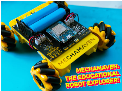
Hi everyone! Earl Daniel Villanueva, the founder of Evtech, and we thrilled to share an exciting project with you today. We’re going to build MechaMaven: The Educational Robot Explorer. This project is not just a fun and engaging activity; it’s a deep dive into the world of robotics, designed to spark curiosity and enhance learning for enthusiasts of all ages. Join me on this journey as we combine innovation, creativity, and hands-on experience to bring MechaMaven to life!
But hey, you might be wondering, Earl, how can you claim that this is an educational robot?
Well, this is specifically designed this for educational purposes. It has 10 output pins to connect 10 sensors or an LCD. It also has 2 output pins for the I2C interface. It includes 4 motor drivers to operate 4 motors, with the option to add up to 6 servo motors. Also, it is equipped with a passive buzzer to play music, and much more! This robot can be controlled using a PS3 controller, a mobile phone, and a computer. But for today’s video, we are going to focus on controlling this robot using a PS3 controller.
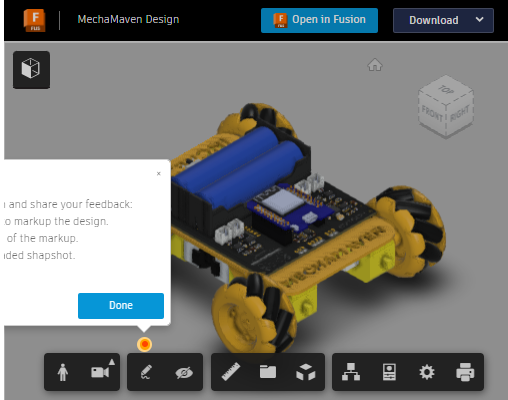
MechaMaven Design
Supplies


Let’s start with the things you will need: 4 pcs of DC geared motor, Mecanum left and right wheel pair, 4 pcs of 2-pin female JST connector, 4 pcs of 2-pin male JST connector, 2 pcs of 18650 battery, 1 pc of 18650 battery holder, a male header pin, 1 pc of slide switch, a female header pin, an ESP32 D1 Mini, 2 pcs of 4-pin female JST connector, 2 pcs of 3-pin female JST connector, a PS3 controller, a mini USB, a micro USB, the PCB, a PCB stencil, 8 pcs of 2.7mm x 29mm screws and their nuts, 4 pcs of 1.8mm x 10mm screws and their nuts, a 3D-printed spacer, and the 3D-printed body.
Components:
1. DC geared motor – 4 pcs
2. Mecanum left and right wheel pair – 1 pair
3. 2-pin female JST connector – 4 pcs
4. 2-pin male JST connector – 4 pcs
5. 18650 battery – 2 pcs
6. 18650 battery holder – 1 pc
7. Male header pin – 1 pc
8. Slide switch – 1 pc
9. Female header pin – 1 pc
10. ESP32 D1 Mini – 1 pc
11. 4-pin female JST connector – 2 pcs
12. 3-pin female JST connector – 2 pcs
13. PS3 controller – 1 pc
14. Mini USB – 1 pc
15. Micro USB – 1 pc
16. PCB – 1 pc
17. PCB stencil – 1 pc
18. 2.7mm x 29mm screws and their nuts – 8 pcs
19. 1.8mm x 10mm screws and their nuts – 4 pcs
20. 3D-printed spacer – 4 pc
21. 3D-printed body – 1 pc
Surface-Mount Device (SMD) Components:
1. L9110S IC – 4 pcs
2. 0.1 µF capacitor – 2 pc
3. 10k resistor – 2 pc
4. 22 µF capacitor – 2 pc
5. 10 µH inductor – 2 pc
6. 26.1k variable resistor – 2 pc
7. MP2307 IC – 2 pc
8. 10k resistor – 2 pc
9. 3.9 nF capacitor – 2 pc
10. 6.8k resistor – 2 pc
11. 0.1 µF capacitor – 2 pc
12. 100k resistor – 2 pc
13. 10 µF capacitor – 4 pc
14. LED indicator light – 1 pc
15. 1k resistor – 1 pc
For the hand tools and fabrication machines, you will need a soldering iron, a soldering pump, soldering wire, soldering lead, a hot air SMD rework station, solder paste, tweezers, and a 3D printer to print the body of the robot.
Hand Tools and Fabrication Machines:
1. Soldering iron
2. Soldering pump
3. Soldering wire
4. Soldering lead
5. Hot air SMD rework station
6. Solder paste
7. Tweezers
8. Phillips Screwdriver
9. Wire Splicer
10. 3D printer (to print the body of the robot)
If you are interested in the PCB Gerber file. You can find it in the GitHub file package link. You can buy 10 pieces of the board for $5 (be sure to input 10pcs. since 5pcs is set by default). I do appreciate it when you buy from my PCBway link, I use the commission to fund my other projects and tutorials, your support would be much appreciated.
GitHub Link: https://github.com/earldanielph/MechaMaven
Step 1: 3D Print Some Parts


The first thing we need to do is print the body of this robot, followed by printing these 4 pieces of spacer.
Chasis Design
https://gmail1612913.autodesk360.com/shares/public/SH30dd5QT870c25f12fcae256fab665639e0
Spacer
https://gmail1612913.autodesk360.com/shares/public/SH30dd5QT870c25f12fc808aafcc82bd362f
Step 2: Soldering Time!


First, we need to place the stencil on top of the PCB. Then, apply a decent amount of solder paste and spread it over the holes in the stencil. After doing that, remove the stencil from the PCB.
Next, place all the SMD components, starting with the L9110S IC, followed by the 0.1 uF capacitor, and the 10k resistor. From this point, I’ll just list the names and values of the components based on their placement on the PCB: a 22uF capacitor, a 10 uH inductor, a 26.1K variable resistor, an MP2307 IC, a 10K resistor, a 3.9 nF capacitor, a 6.8K resistor, a 0.1 uF capacitor, a 100K resistor, and two 10 uF capacitors. Repeat this process on the other side of the PCB. Also, don’t forget the LED indicator light and the 1K resistor. Look at that! It really looks awesome! Now, using a hot air rework station, melt the solder paste, which will effectively position the components correctly.
After that, it’s time to solder all the THT components, starting with the 2-pin JST female connector, followed by the slide switch. Next, solder the 3-pin and 4-pin JST female connectors, the 18650 battery holder, the passive buzzer, and the female header pin for the ESP32.
And there you have it, we’re done placing all the components on the PCB.
Yes, of course, I have provided the Gerber files and the schematic diagram for this project.
Now, it’s time to solder the male header pins of the ESP32.
Attachments
Step 3: The 3D Printed Body


Now it’s time to attach the PCB to the 3D-printed body. Start by inserting the 4 pieces of 1.8mm x 10mm screws into the PCB, making sure to place the spacers between the PCB and the 3D-printed body. After that, secure them with the nuts.
Step 4: The Motor


Of course, this robot car will not work without the motors. We need to attach all 4 motors to the 3D-printed body first. Secure them in place using the 2.7mm x 29mm screws and their nuts.
Step 5: Solder the Wires of the Motor


In this part of the tutorial, we need to do some soldering again. We need to solder wires from the PCB to the motors, and we will use the 4 pieces of 2-pin male JST connectors.
For the orientation of this robot, remember that this is the front part. If you look closely at the PCB, there are indicators showing where to connect the wires from the motors to the PCB. For instance, “MFR” stands for Motor Front Right, meaning this is where you will connect the wire from the front right motor of the robot to the PCB. So make sure to take note of that.
Step 6: The Mecanum Wheel


Now, we need to attach the Mecanum wheels to the shafts of the motors. Before doing this, make sure you are placing the wheels in the correct orientation. The Mecanum wheel has a specific mechanism and will not work properly if it is not placed correctly.
If you look closely at the Mecanum wheel, there are labels indicating whether it is for the right or left side of the robot. So in this case, since these are the wheels for the right side, I’ll attach these two wheels to the right side, and the other two to the left side of the robot.
Step 7: Downloading the Arduino IDE


It’s programming time! But before we can program the ESP32, we need to download the Arduino IDE. First, go to the Arduino website and download the Arduino IDE.
After clicking the download button, wait for the download to complete. Once done, we need to install the Arduino IDE. Click on the downloaded file, and follow the installation steps: click “I agree,” then “Next,” and finally “Install.” Once the installation is complete, click the “Finish” button to run the Arduino IDE.
Link: https://www.arduino.cc/en/software
Step 8: Downloading the Code


We need to open the browser again and go to my GitHub repository to download the code. You can do this by typing github.com/earldanielph.
After that, all my repositories will appear, and you need to click on “MechaMaven.” Once there, click on “Code,” and download it as a zip file.
Click on the downloaded file, right-click, and extract the file. Then, open the “MechaMavenByEvtech” code.
Link: https://github.com/earldanielph/MechaMaven
Step 9: Downloading the Necessary Library


This time, we need to download the PS3 Controller library. Copy this part of the code and paste it into your browser. Click on this link and then this one. Click on the code and download it as a zip file. After that, go to Sketch, include library, add .ZIP library, and select the downloaded library file.
Link: https://github.com/jvpernis/esp32-ps3/tree/master
Step 10: Downloading the ESP32 Board Manager


Go back to your browser and type ‘ESP32 download manager’. Click on this link, scroll down a bit, copy the URL. Return to your Arduino IDE, click on ‘File’, then ‘Preferences’. Click on this, and paste the URL you copied from the website earlier. Click ‘OK’, and then click here. Now, go to ‘Board Manager’, type ‘ESP32’, and install the ESP32 board manager under Espressif Systems.
Link: https://randomnerdtutorials.com/installing-the-esp32-board-in-arduino-ide-windows-instructions/
Step 11: Downloading Sixaxis Pair Tool


Now, return to your browser to download the Sixaxis Pair Tool. Type ‘Sixaxis’ into your browser, click on this link, and hit the download button. Just wait for it to start downloading. Once it’s done, open the file, click ‘Next’, then ‘Next’ again, click here, and hit ‘Install’. Once installation is complete, click ‘Finish’.
Link: https://sixaxispairtool.en.lo4d.com/windows
Step 12: Getting the MAC Address of the PS3 Controller


This time, we need to open the Sixaxis Pair Tool and insert the USB cable from the computer into the PS3 controller. Once you’ve done that, the MAC address of your controller will appear on the Sixaxis Pair Tool.
In my case, this is my MAC address, and I will type it into my code. After getting your MAC address, you can now remove the USB cable from your computer going to your PS3 controller.
Step 13: Uploading the Code to ESP32


And finally, we are now going to upload the code to the ESP32. Make sure to connect the micro USB cable from your computer to your ESP32. Now, click on ‘Tools’, then ‘Board’, select ‘Wemos D1 Mini ESP32’. Click on ‘Tools’ again, then ‘Port’, and choose the appropriate port for your ESP32. In my case, it is COM24. Finally, click ‘Upload’.
Once the uploading is done, you can now remove the micro USB cable from your ESP32 and connect your ESP32 to your PCB.
Step 14: Demo

There you have it—the project is completed! It’s time to sit back and enjoy the fruits of your labor.
Step 15: Enjoy!
